43
A7 -- Fuse Chart
Unit Size
Fuse Rating (Amps/Volts)
Indoor Outdoor Outdoor
009 --- 3.15A/250V 2A/250V
012 --- 3.15A/250V 2A/250V
018 3.15A/250V 3.15A/250V ---
024 3.15A/250V 3.15A/250V ---
The 3.15A fuses protect the board against the indoor or outdoor fan motors.
The 2A fuses protect the board against a Class II circuit board failure.
A8 -- Indoor Unit Diagnostic Guid es
9K & 12K Units
Operation
Lamp
Timer
Lamp
Failure Mode
Diagnostic
Chart
l X Indoor fan speed has been out of control for over 1 minute 1
l On Indoor room temp. or evaporator sensor is open circuit or short circuited 2
X l Compressor over--- current protection has been activated four times 3
On l EPROM error* ---
l l Indoor unit communication error (Illuminates simultaneously) 4
18K & 24K Units
Opera-
tion
Lamp
Timer
Lamp
Defrosting
Lamp
Auto
Lamp
Failure Mode
Diagnostic
Chart
l l l l Over--- current protection of the compressor occurs four times 3
X l X X Indoor room temp. sensor is open circuit or short circuited 2
l X X X Temp. sensor on indoor evaporator is open circuit or short circuited 2
X X l X
Temp. sensor on outdoor condenser is open circuit or short circuited (not
cooling only modes)
2
X X l l Outdoor unit protects (outdoor temp. sensor, phase order, etc.) 5
X l X l EP ROM error* ---
X X X l Indoor unit communication error 6
l =Flashing
X=Off
* = Replace Indoor Board
A07545a
A07544
A07546a
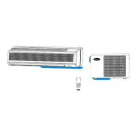
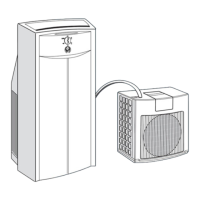
Model size 009
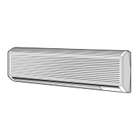
Model size 012
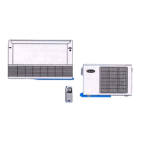
Model size 018-- 024*
Infrared signal receptor
OPERATION
TIMER
PRE-DEF
AUTO
ECON
TIMER
OPERATION
PRE-DEF
Infrared signal recepto
* PRE--DEF light will illuminate when the unit is running in FAN ONLY mode on Cooling Only units.
AUTO
TIMER
PRE.-DEF.
OPERATION
Fig. 34 – LED Display Panel
A9 -- Outdoor Unit Diagnostic Guides
Flashing
Times after 2
Second Off
Failure Mode
Diagnostic
Chart
5 C ommunication failure 4or6
2 C ondenser temperature sensor failure 2
1 O ther indoor failure –
If the unit is operating normally, the LED light on the outdoor board is lit continuously. If there is a failure, the LED light will flash a specific
number of times. Refer to the Outdoor Unit Diagnostic table above to determine failure.
38/40MVC, MVQ

 Loading...