FMC5X, FMC5Z: Installation Instructions
Manufacturer reserves the right to change, at any time, specifications and designs without notice and without obligations.
6
All units are shipped from factory wired for 240VAC transformer
operation. For 208VAC operation, move primary lead from 240VAC
terminal to 208VAC terminal.
See Fig. 4, and Fig. 5 for field low-voltage wiring See Fig. 2 for location
of the electrical inlets. For maximum ampacity and over--current
protection, see unit rating plate or product data sheet.
1. Provide power supply for unit being installed in accordance with
unit wiring diagram and rating plate.
2. Connect line-voltage leads to the harness pigtail or the heat-kit
terminal block. Use copper wire only.
3. Use UL listed conduit and conduit connector for connecting
line-voltage leads to unit and obtaining proper ground. If conduit
connection uses reducing washers, a separate ground wire must be
used. Grounding can also be accomplished by using the ground lug
provided in the control box. Power wiring may be connected to
either the right or left sides or top of unit. Knockouts of 7/8" (22
mm) dia. are provided for connection of power wiring to unit. Some
heater sizes may require a conduit larger than the 7/8" opening; in
this situation the high-voltage connection opening should be
enlarged to fit the conduit. When removing the knockouts for
electrical connections, an opening in the insulation should be cut to
fit the opening. The cut edge of the insulation should be reinforced
with foil tape to prevent fraying. The foil facing and insulation shall
not be removed beyond the knockout opening size.
4. Install plastic grommet packed with unit in hole for low-voltage
wires.
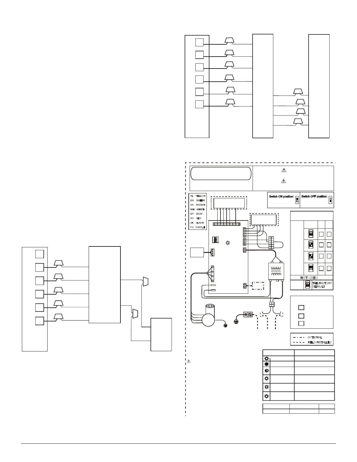
5. Connect low-voltage leads to thermostat and outdoor unit. See
Fig. 4, and Fig. 5 as well as the outdoor unit wiring label.
NOTE: For field installed electric heat, the leads from the 6-pin
connector (L1 and L2) will need to be disconnected so the electric heat
can plug into that connector. Refer to Fig. 6 and Fig. 7, and the electric
heat installation instructions for more details.
A150158A
Fig. 4 – Wiring Layout Air Conditioning Unit
(Cooling and 1-Stage Heat)
A150159A
Fig. 5 – Wiring Layout Heat Pump Unit
(Cooling and 2-Stage Heat)
A240336
Fig. 6 – Wiring Diagram - PSC
O/B
W1
Y1 Y
Y
R
CC
C
AIR COND.
G
O/B
THERMOSTAT
FAN COIL
(CONTROL)
WHITE
YELLOW
YELLOW
RED
BLACK
BLACK
GREEN
W
Y1
R
C
G
W1
Y1
C
O/B
Y
W
C
O/B
Y
W
R
C
G
O/B
ORANGE
THERMOSTAT
FAN COIL
(CONTROL)
HEAT PUMP
(CONTROL)
WHITE
YELLOW
RED
BLACK
GREEN
YELLOW
WHITE
ORANGE
BLACK
O/B
W
Y1
R
C
G
CO M
208 V
240 V
Cn1 7
De TAILE D REFERENC E
MANUA L INSTRUCTION S
LED 1
CONTRO L BOAR D
Sw6-1, 2
Sw6-3, 4
24 V
TRANSFORME R
G W/W 1
L
L
M
H
H
H
HH
FAN spee d
t ap s
1 2 3 4
ON
R454B
SENSOR
CAPACI TOR
SW6
RD
BK
cn1 4
cn 11
cn3 3
YL
OR
YL
WH
WH
pu
BK
BK
YL
cn2 6
Cn3 4
TO THERMOSTAT
ALARM
L M H N
Cn 7
Cn 8
bk
WH
OR
GR
RD
YL
BR
BR
O/ B
W1
Y1
R
W
W
Y
Y
C
C
C
W1
O/ B
O/ B
C
G
O/ B
W1
Y1
R
C
G
Cn3 6
SPEE D TAP S
L
Lo w
H
HIG H
M
MEDIU M
STEADY ON
NORMAL OPERATION
POWER SUPPLY FAILURE
4 FLASH/CYCLE
3 FLASH/CYCLE
OFF
0
3
LED1 STATUS
CONTENT
4
STEADY FLASHING
REFRIGERANT LEAK
PROTECTION
1 2
ON
1 2
ON
1 2
ON
1 2
ON
3 4
ON
Factory code Date Revision
Jan. 26th, 2024 B
NOTES:
1: Connect R to R, G to G, Y to Y, etc. See outdoor
instruction for details.
2: If some signal lines of CN36 are not used,
please wrap them up separately with CAP.
CAUTION:
1: Use copper wire (75℃ min) only between
disconnect switch and unit.
2: To be wired in accordance with NEC and local
codes.
3: If any of the original wires, as supplied, must be
replaced. Use the same or equivalent type wires.
4: If the input voltage is 208 V, please change the
transformer tap by taking the red wire to 208V
terminal.
5: The rated operating condition of Alarm is 24
VAC/1A or 30 VDC/1A or 250 VAC/1A.
FAN
MOTOR
indoo r f a n mo t o r
l
m
h
n
OPTIONAL
FIELD INSTALLED
1
ON
1
ON
NOT USED
THE FACTORY
DEFAULT
R454B REFRIGERANT SENSOR
COMMUNICATION FAULT
R454B REFRIGERANT
SENSOR FAULT
8 FLASH/CYCLE
8
R454B REFRIGERANT SENSOR
OVER SERVICE LIFE
PLU G
PL ATE
YL YELLO W
GR GREE N
BR BROW N
WH WHIT E
GY GR AY
RD RE D
BK BLAC K
PU PURPL E
1
2
3
4
5
6
1
2
3
4
5
6
TO OUTDOOR UNIT
WIRING DIAGRAM
SEE NAME PLATE FOR VOLT&HERTZ
FIELD POWER WIRING
CAUTION:
NOT SUITABLE FOR USE ON SYSTEMS EXCEEDING 150V TO GROUND.
ATTENTION:
NE CONVIENT PAS AUXINSTALLATIONS DE PLUS DE 150V ALA TERRE.
DI P SWITC H
12
12
PLUG2- A
PLUG1- A
PLUG1- B
PLUG2- B
18/24/36 K
30 K
Switch ON position:
Switch position
is UP for ON
Switch OFF position:
Switch position
is DOWN for OFF
GROUN D
Plu g
POWE R IN
L1
L2
PE
BK
RD
CLASS 2
CLASS 2