1. W2
When thermostat sends a signal to W2, a 24-vac signal is
applied across sequencer/relay number 1, causing it to close.
When sequencer/relay number 1 closes, first stage of electric
heat is energized. In straight electric heat, fan is also energized
through the normally-closed contacts of fan relay. In cooling,
heat pump, or manual fan mode, fan will already be running
since fan relay would have been energized. When thermostat
stops calling for electric heat, the 24-vac signal to
sequencer/relay number 1 turns off and sequencer opens after
a delay of 60 to 90 sec. Heaters equipped with relays will be
de-energized immediately. When sequencer/relay opens, first
stage of heat turns off along with fan, providing thermostat is
not calling for the fan.
2. W3
When a signal is sent to W3, a 24-vac signal to
sequencer/relay number 2 causes it to close, with second stage
of electric heat turning on. The 24-vac signal applied to
sequencer/relay number 1 causes fan to operate. Timing is
such that sequencer/relay number 1 will turn on before
sequencer/relay number 2. When signal to W3 is turned off,
sequencer/relay number 2 opens. If W2 is also satisfied, first
stage of electric heat and fan will also turn off, providing
thermostat is not calling for the fan.
3. E
When thermostat sends a signal to E, a 24-vac signal is sent to
sequencer/relay number 3. The 24-vac signal applied to
sequencer/relay number 3 turns on third stage of electric heat.
The 24-vac signal applied to sequencer/relay number 1 turns
on first stage of electric heat and fan. When thermostat stops
calling for electric heat, the signal to sequencers/relays 1, 2,
and 3 are turned off, and sequencers/relays open. This causes
electric heat to turn off with fan providing thermostat is not
calling for the fan.
NOTE: Electric heaters are factory wired with all stages tied
together. If independent staging is desired, consult outdoor ther-
mostat installation instructions, or corporate thermostat instruc-
tions.
Step 3—Troubleshooting the Printed-Circuit Board
Use wiring schematics shown in Fig. 4 and 5 as a guide in
troubleshooting PCB unless otherwise noted.
IF FAN WILL NOT TURN ON FROM THERMOSTAT:
If There Is No High Voltage To Transformer:
1. Check plug/receptacle connection. This supplies power from
heaters to PCB Fan Relay. Be sure plug is connected properly.
2. Check sequencer/relay number 1 and plug wiring. Yellow
wire should be connected to pin number 9 of plug and to limit
switch. Black wire should be connected to pin number 7 of
plug and to sequencer/relay number 1.
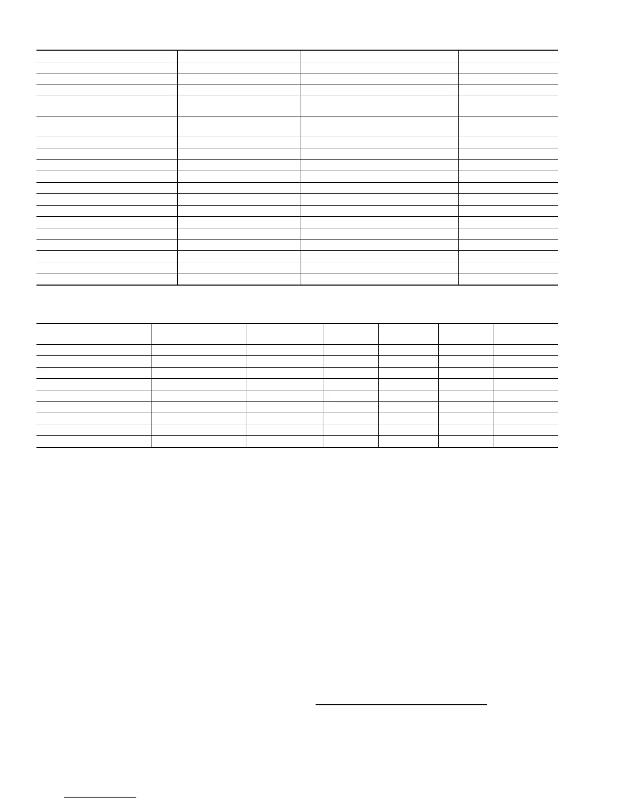
Table 1—Product Offering
MODEL UNIT SIZE DESCRIPTION CABINET
FA4ANF 018-060 Multipoise Single Piece
FB4ANB 042-070 Multipoise Modular
FB4ANF 018-060 Multipoise Single Piece
FB4ASB 042-060
Multipoise
50 Hz
Modular
FB4ASF 018-060
Multipoise
50 Hz
Single Piece
FC4BNB 042-070 Multipoise Modular
FC4BNF 024-060 Multipoise Single Piece
FD3ANA 018-030 Horizontal Single Piece
FF1A/FF1B/FF1C/FF1D 018-030 Vertical Single Piece
FG3ANA 024, 036, 048, 060 Horizontal/Small Commercial Single Piece
FH4ANB 003, 004 Multipoise Modular
FH4ANF 001-004 Multipoise Single Piece
FK4CNB 006 Multipoise Modular
FK4CNF 001-005 Multipoise Single Piece
FX4ANF 030-048 Multipoise Single Piece
FX4ANB 060 Multipoise Modular
FV4ANF 002, 003, 005 Multipoise Single Piece
FV4ANB 006 Multipose Modular
NOTE: Multipoise units are approved for upflow, downflow, and horizontal left and right applications.
Table 2—PSC Fan Motor Speed Taps
MODEL
UNIT
SIZE
NUMBER OF
SPEEDS
HIGH
SPEED
MEDIUM
SPEED
LOW
SPEED
COMMON
FA4A 018-036 2 Black — Blue Yellow
FA4A 042-060 3 Black Blue Red Yellow
FB4A 018-070 3 Black Blue Red Yellow
FC4B 024-070 3 Black Blue Red Yellow
FD3A 018-030 2 Black — Red Yellow
FF1A/FF1B/FF1C/FF1D 018-030 2 Black — Red Violet**
FG3A 024, 036, 048, 060 1* — — — —
FH4A 001-004 3 Black Blue Red Yellow
FX4A 030-060 3 Black Blue Red Yellow
*Belt drive.
→**Yellow on FF1D
4