10
AIRFLOW PERFORMANCE TABLES
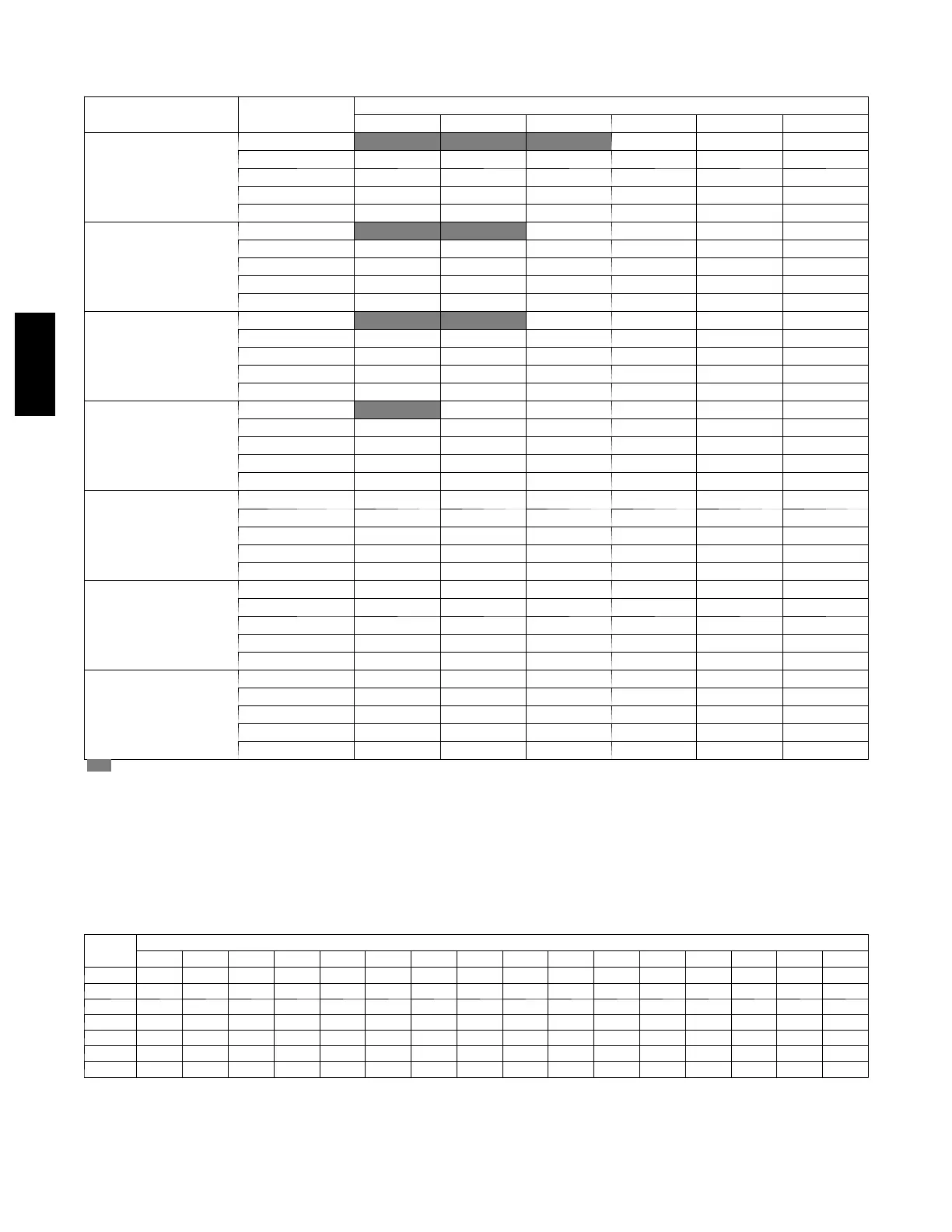
Table 1 – Airflow Performance (CFM)
MODEL & SIZE BLOWER SPEED
EXTERNAL STATIC (in. wc)
0.10 0.20 0.30 0.40 0.50 0.60
FX4D 019
Tap 5 776 745 696 660 609 572
Tap 4 683 644 589 548 494 461
Tap 3 683 644 589 548 494 461
Tap 2 631 563 500 443 409 361
Tap 1 625 524 457 417 367 319
FX4D 025
Tap 5 956 920 891 851 816 780
Tap 4 825 795 757 722 674 634
Tap 3 825 795 757 722 674 634
Tap 2 726 695 635 598 543 509
Tap 1 631 563 500 443 409 361
FX4D 031
Tap 5 1189 1151 1104 1050 1003 959
Tap 4 1041 998 944 886 837 772
Tap 3 1041 998 944 886 837 772
Tap 2 924 876 817 752 704 660
Tap 1 779 693 628 571 526 476
FX4D 037
Tap 5 1363 1332 1294 1253 1207 1157
Tap 4 1237 1206 1160 1121 1070 1013
Tap 3 1237 1206 1160 1121 1070 1013
Tap 2 1095 1058 1007 951 888 824
Tap 1 1014 885 773 673 609 549
FX4D 043
Tap 5 1519 1490 1454 1419 1379 1332
Tap 4 1437 1403 1366 1333 1294 1245
Tap 3 1437 1403 1366 1333 1294 1245
Tap 2 1257 1226 1191 1141 1090 1033
Tap 1 1237 1206 1160 1121 1070 1013
FX4D 049
Tap 5 1757 1725 1693 1653 1614 1576
Tap 4 1664 1626 1593 1552 1517 1477
Tap 3 1664 1626 1593 1552 1517 1477
Tap 2 1459 1420 1379 1336 1298 1259
Tap 1 1301 1241 1195 1150 1102 1039
FX4D 061
Tap 5 2030 1995 1961 1927 1888 1842
Tap 4 1811 1775 1740 1703 1664 1613
Tap 3 1811 1775 1740 1703 1664 1613
Tap 2 1665 1632 1593 1556 1507 1453
Tap 1 1462 1418 1371 1327 1278 1228
--- S h a d i n g --- Ai r f l o w o u t s i d e 4 5 0 c f m / t o n .
NOTES:
1. Airflow based upon dry coil at 230v with factory approved filter and electric heater (2 element heater sizes 019 through 037, 3 element heater sizes
043 through 061).
2. Airflow at 208 volts is approximately the same as 230 volts because the X13 motor is a constant torque motor. The torque doesn’t drop of f at the
speeds the motor operates.
3. To avoid potential for condensate blowing out of drain pan prior to making drain trap:
Return static pressure must be less than 0.40 in. wc.
Horizontal applications of 043 --- 061 sizes mu st have supply static greater than 0.20 in. wc.
4. Airflow above 400 cfm/ton on 049 --- 061 size could result in condensate blowing off coil or splashing out of drain pan.
Table 2 – Air Delivery Performance Correction Component Pressure Drop (in. wc) a t Indicated Airflow (Dry to Wet Coil)
FX
Size
CFM
500 600 700 800 900 1000 1100 1200 1300 1400 1500 1600 1700 1800 1900 2000
019 0.034 0.049 0.063 --- --- --- --- --- --- --- --- --- --- --- --- --- --- --- --- --- --- --- --- --- --- --- --- --- ---
025 0.016 0.027 0.038 0.049 0.059 --- --- --- --- --- --- --- --- --- --- --- --- --- --- --- --- --- --- --- --- --- ---
031 --- --- --- --- --- --- 0.049 0.059 0.070 0.080 --- --- --- --- --- --- --- --- --- --- --- --- --- --- --- --- --- ---
037 --- --- --- --- --- --- --- --- --- --- 0.055 0.064 0.073 0.081 --- --- --- --- --- --- --- --- --- --- --- --- --- ---
043 --- --- --- --- --- --- --- --- --- --- --- --- --- --- 0.049 0.056 0.063 0.070 --- --- --- --- --- --- --- --- --- ---
049 --- --- --- --- --- --- --- --- --- --- --- --- --- --- --- --- --- --- 0.038 0.043 0.049 0.054 0.059 --- --- --- ---
061 --- --- --- --- --- --- --- --- --- --- --- --- --- --- --- --- --- --- --- --- --- --- 0.027 0.031 0.035 0.039 0.043
FX4D

 Loading...