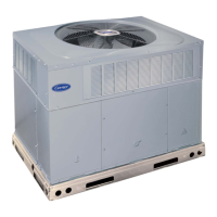
UNIT SIZE
Weight A B C D E F
Lb Kg mm ft-in. mm ft-in. mm ft-in. mm ft-in. mm ft-in. mm ft-in.
50DJ,DK,NP
054 7700 3493
5537 18-2 1163 3-9
13
⁄
16
10,476 34-4
7
⁄
16
2864 9-4
3
⁄
4
10,092 33-1
5
⁄
16
5347 17-6
1
⁄
2
064 8000 3629
074 8430 3824 5969 21-3 1163 3-9
13
⁄
16
11,385 37-4
1
⁄
4
3727 12-2
3
⁄
4
11,001 36-1
1
⁄
8
4483 14-8
1
⁄
2
LEGEND
CONN — Connection
DIM — Dimension
*Dimension shown is for 48 series units. On 50 series units, dimension given
is measured from economizer end of unit to drain connection closest to con-
denser fans.
NOTES:
1. Dimensions in [ ] are in millimeters.
2. Center of Gravity includes economizer. Unit weight does not include
economizer.
3. Unit clearances:
Top — Do not restrict condenser fans
Control Box End — 68-09
Sides — 68-09 (except power exhaust units 108-09)
Economizer End — 68-09 (except power exhaust units 108-09)
For smaller service and operational clearances, contact Carrier Product En-
gineering Department.
4. Vertical discharge ducts designed to be attached to accessory roof curb. If
unit is mounted on dunnage, support the ducts using cross braces as done
on the accessory roof curb.
5. When unit is slab mounted, locate the condensate drain as low as possible
on vertical face of base rail at the same location as the standard conden-
sate drain (using factory supplied fitting). Plug factory drilled condensate
hole.
Fig. 4D — Base Unit Dimensional Drawing; 50DJ,DK,NP054-074 Units
14