Manufacturer reserves the right to discontinue, or change at any time, specifications or designs without notice and without incurring obligations.
PC 111 Catalog No. 535-00137 Printed in U.S.A. Form 50BV,XJ-2T Pg 1 2-04 Replaces: 50BV,XJ-1T
Book 1 1
Tab 2 a 2 b
Controls Operation and
Troubleshooting
CONTENTS
SAFETY CONSIDERATIONS......................1
GENERAL ........................................ 1
MAJOR SYSTEM COMPONENTS ...............1-7
Comfort Controller Processor (PCB1) ............1
Comfort Controller I/O Module (PCB2)............2
Comfort Controller I/O Module (PCB3)............2
Local Interface Display ...........................2
PCB Addresses .................................. 2
Control Module Communication..................2
Carrier Comfort Network Interface................4
Optional and Field-Installed
Accessory Sensors/Devices ................... 4
Wiring Control Devices...........................6
CONTROLS AND FUNCTIONS................. 8-15
Using the Local Interface Display ................8
Automatic Run Test .............................10
Power Up the LID Display .......................12
Log On to the LID Display .......................12
Change the Default Password ...................12
Set the Clock....................................12
Configure Schedules............................13
Program Set Points .............................13
Check System Parameters ......................14
Display Alarm History ...........................14
Configure Custom Programming Selections ....14
Set Controller Address ..........................15
Log Off from Controller .........................15
OPERATION.................................. 16-26
Occupancy Determination.......................16
Fan Control .....................................16
Sequence of Operation..........................16
Diagnostic Features.............................18
50XJ Variable Frequency Drive Control..........19
50BV Variable Frequency Drive Control .........22
TROUBLESHOOTING......................... 27-29
Run Test Troubleshooting.......................27
Forcing and Clearing and Input or Output .......27
Standard Diagnostic Features,
Alarm and Warning Lights ....................28
APPENDIX A — WIRING DIAGRAMS ......... 30-42
APPENDIX B — CONTROL SCREENS ........ 43-64
Display Screens.................................43
Configuration Screens ..........................45
Maintenance Screens ...........................58
SAFETY CONSIDERATIONS
Installing, starting up, and servicing this equipment can be
hazardous due to system pressures, electrical components, and
equipment location. Only trained, qualified installers and
service mechanics should install, start up, and service this
equipment.
When working on this equipment, observe precautions in
the literature; on tags, stickers, and labels attached to the equip-
ment, and any other safety precautions that apply. Follow all
safety codes. Wear safety glasses and work gloves. Use care in
handling, rigging, and setting this equipment, and in handling
all electrical components.
GENERAL
This publication contains Start-Up, Controls Operation, and
Troubleshooting information for the 50BV,XJ units. These
OMNIZONE™ packaged units are self-contained, water-
cooled or remote air-cooled indoor units for use in VAV
(variable air volume) applications. Units are equipped with
Comfort Controller 6400 (CC6400) system controls. Refer to
the unit Installation Instructions for unit layout.
MAJOR SYSTEM COMPONENTS
Comfort Controller Processor (PCB1) —
The central processing unit for the OMNIZONE system
control is the Comfort Controller 6400. The Comfort Control-
ler provides general purpose HVAC (heating, ventilation and
air conditioning) control and monitoring capability in a stand-
alone or network environment using closed-loop, direct dig-
ital control. The Comfort Controller 6400 has been pre-pro-
grammed to work in either stand-alone or CCN (Carrier Com-
fort Network) system installations.
The CC6400 processor is designed to provide heating and
cooling control, loop control, scheduling, and custom program-
ming. The main processor provides 16 field points (8 input and
8 output). Additional points are provided by the I/O modules
described on page 2. Table 1 lists the control inputs and outputs
for all CC6400 modules.
Specifications for the Comfort Controller 6400 may be
found in the Comfort Controller literature.
Electrical shock can cause personal injury and death.
Shut off all power to this equipment during installation
and service. There may be more than one disconnect
switch. Tag all disconnect locations to alert others not to
restore power until work is completed.
This unit uses a microprocessor-based electronic control
system. Do not use jumpers or other tools to short out
components, or to bypass or otherwise depart from rec-
ommended procedures. Any short-to-ground of the con-
trol board or accompanying wiring may destroy the
electronic modules or electrical components.
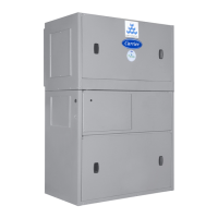
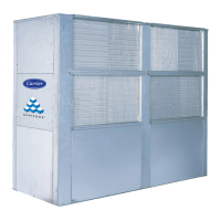
OMNIZONE™
50BV020-064, 50XJ064-104
Indoor Self-Contained
Remote Air-Cooled and Water-Cooled, VAV Systems
18 to 100 Nominal Tons