Manufacturer reserves the right to discontinue, or change at any time, specifications or designs without notice and without incurring obligations.
Catalog No. 04-53500190-01 Printed in U.S.A. Form 50BV-6SI Pg 1 11-21 Replaces: 50BV-5SI
Installation, Start-Up, Service and Controls
Operation and Troubleshooting
CONTENTS
Page
SAFETY CONSIDERATIONS . . . . . . . . . . . . . . . . . . . 2
GENERAL . . . . . . . . . . . . . . . . . . . . . . . . . . . . . . . . . . . 3
MAJOR CONTROL COMPONENTS . . . . . . . . . . . . . . 3
Constant Volume (CV) Units . . . . . . . . . . . . . . . . . . . 3
• UNIT PROTECTION MODULE (UPM)
Variable Air Volume (VAV) Units . . . . . . . . . . . . . . . . 4
PRE-INSTALLATION . . . . . . . . . . . . . . . . . . . . . . . . . . 4
INSPECTION . . . . . . . . . . . . . . . . . . . . . . . . . . . . . . . . 4
• UNIT STORAGE
INSTALLATION . . . . . . . . . . . . . . . . . . . . . . . . . . . . . . 4
Step 1 — Check Equipment . . . . . . . . . . . . . . . . . . . . 4
Step 2 — Check Jobsite . . . . . . . . . . . . . . . . . . . . . . . 4
• UNIT LOCATION
• INSTALLATION GUIDELINES (ALL UNITS)
• UNIT PLACEMENT
• ACOUSTICAL CONSIDERATIONS
Step 3 — Rig and Place Unit . . . . . . . . . . . . . . . . . . . 5
• SINGLE PIECE UNITS (50BVC,J,Q)
• MODULAR UNITS (50BVT,V,W)
• LOW BOY UNITS
• HIGH BOY UNITS
• REMOVE PACKAGING
• ASSEMBLING MODULAR UNITS
Step 4 — Install Ductwork . . . . . . . . . . . . . . . . . . . . 21
• DUCT STATIC PRESSURE PROBE AND TUBING
(VAV ONLY)
• DUCT HIGH-STATIC (DHS) LIMIT SWITCH (VAV
ONLY)
Step 5 — Make Piping Connections . . . . . . . . . . . . 22
• CONDENSER WATER PIPING
• EVAPORATOR CONDENSATE DRAIN
• HOT WATER HEATING COIL (OPTIONAL)
• WATERSIDE ECONOMIZER (OPTIONAL)
Step 5 — Complete Electrical Connections . . . . . . 25
•POWER WIRING
• CONTROL WIRING (CV ONLY)
• SUPPLY AIR TEMPERATURE SENSOR (SAT)
• SMOKE DETECTOR/FIRE ALARM SHUTDOWN (FSD)
• REMOTE OCCUPANCY (ROCC)
• RETURN AIR TEMPERATURE (RAT) SENSOR
START-UP . . . . . . . . . . . . . . . . . . . . . . . . . . . . . . . . . 32
General . . . . . . . . . . . . . . . . . . . . . . . . . . . . . . . . . . . . 32
• CRANKCASE HEATERS
• CONFIRM THE INPUT POWER PHASE SEQUENCE
• INTERNAL WIRING
• RETURN-AIR FILTERS
• COMPRESSOR MOUNTING
• REFRIGERANT SERVICE PORTS
•WATER PIPING
CV Unit Start-Up . . . . . . . . . . . . . . . . . . . . . . . . . . . . .33
• EVAPORATOR FAN
• COOLING
CONTROLS . . . . . . . . . . . . . . . . . . . . . . . . . . . . . . . . .33
Unit Protection Module (UPM) . . . . . . . . . . . . . . . . .33
• GENERAL DESCRIPTION
• FEATURES AND SAFETIES
Sequence of Operation,
CV Units — 50BVC,Q,T,V . . . . . . . . . . . . . . . . . . .35
• WATER ECONOMIZER COOLING
• Y CALL (COOLING OR HEATING)
I/O Flex 6126 Controller Specifications . . . . . . . . . .37
•POWER
• PHYSICAL
• ENVIRONMENTAL OPERATING RANGE
• DIGITAL OUTPUTS
• ANALOG OUTPUTS
• UNIVERSAL INPUTS
• STANDARD COMMUNICATION PORTS
• RNET PORT
• LOCAL ACCESS PORT
•XNET PORT
• BACNET SUPPORT
• STATUS INDICATION
• BATTERY
• PROTECTION
•LISTED BY
•WEIGHT
• OVERALL DIMENSIONS
• MOUNTING HOLE DIMENSIONS
Addressing the I/O Flex 6126 Controller . . . . . . . . .37
BACnet Protocol Selection . . . . . . . . . . . . . . . . . . . .37
Wiring Inputs and Outputs . . . . . . . . . . . . . . . . . . . .38
Input – I/O Flex 6126 Controller . . . . . . . . . . . . . . . .38
• BINARY OUTPUTS
• ANALOG OUTPUTS
• TO WIRE FIELD ACCESSORIES ON THE I/O FLEX
6126 CONTROLLER OR I/O FLEX EX8160 EXPANDER
I/O Flex EX8160 Expander Module . . . . . . . . . . . . . .41
• GENERAL DESCRIPTION
VAV Control Parameters, Status, and Alarms . . . . .41
Sequence of Operation, VAV Units Only
50BVJ,W . . . . . . . . . . . . . . . . . . . . . . . . . . . . . . . . .43
• CONTROL SOURCE (RUN CONDITIONS)
• EXTERNAL CONTROL SOURCE
•DIGITAL INPUT
•BAS
• MANUAL ON
• INTERNAL CONTROL SOURCE (KEYPAD)
Unit Mode . . . . . . . . . . . . . . . . . . . . . . . . . . . . . . . . . .43
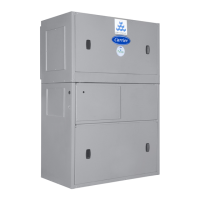
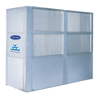
Omnizone™
50BV020-064
Water-Cooled
Indoor Self-Contained Systems