6
dimensions. The filter rack/economizer section of the low boy unit
can be field removed for easier installation. See Fig. 4 and 5 for
low boy field splits.
HIGH BOY UNITS
50BV high boy units are tall and thin and ship in two (034) or four
(044-064) modules that require field assembly (fan section and
main section). See Fig. 8 and 10 for high boy base unit dimen-
sions. The filter rack/economizer can be removed from the main
section to allow all high boy units to fit through a 36" wide open-
ing (the fan assembly needs to be rotated). See Fig. 2 and 3 for
high boy field splits.
Refer to Fig. 7-12 for unit dimensions. Refer to Tables 2 and 4 for
physical data.
REMOVE PACKAGING
Remove all protective plastic and other supports only after the
units have been installed. Remove and discard unit top cover pro-
tector, filter cover, controller display protector, remove any includ-
ed shipping supports, and water piping connection packaging.
ASSEMBLING MODULAR UNITS
50BVT,V,W unit sizes 034-064 ship in pieces. Reassemble the
unit. Use the loose hardware provided in the main air-conditioning
section and the instructions below.
1. The filter/economizer section ships bolted to the main air-
conditioning section and can be removed in the field (high
and low boy units). When reattaching the filter/economizer
section to the main air-conditioning section, place the filter
side of the filter/economizer section facing out and away
from the main air-conditioning section.
2. If the unit has two filter/economizer and two main air-condi-
tioning sections (unit sizes 044-064), bolt the remaining filter/
economizer section and main air-conditioning section
together, as in Step 1.
3. For units with two filter/economizer and two main air-con-
ditioning sections, use the provided unions to assemble the
water connections between the two additional sections
joined in Step 2.
4. For unit sizes 044-064, connect the condensate drain hoses
from the “B” side of the unit to the drain manifold on the “A”
side of the unit.
5. For unit sizes 044-064, connect power wiring from the main
terminal block in the “A” side of the unit to the power termi-
nal block in the “B” side of the unit.
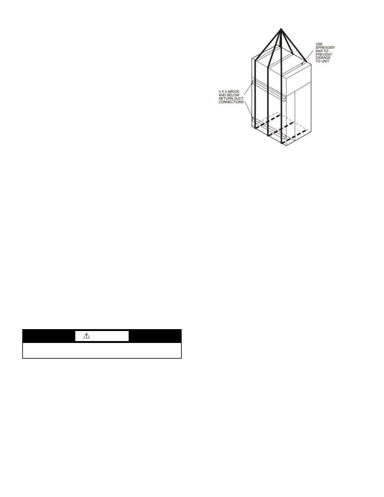
Fig. 1 — Modular Unit Rigging
CAUTION
Remove all shipping blocks, if any, under blower housing or
damage to the fan may occur.
 Loading...