71
Fan Bearing Lubrication
Inspect the fan bearings for proper lubrication every 6 month or
2500 hours of operation, whichever comes first. Standard units
have grease fittings on the fan shaft bearings, located on each side
of the blower wheel. Lubricate bearings with a lithium-based
grease (NLGI Grade 2).
Fan Sheaves
Factory-supplied drives are pre-aligned and tensioned; however, it
is recommended that the belt tension and alignment be checked
before starting the unit. Always check the drive alignment after
adjusting belt tension.
To install sheaves on the fan or motor shaft:
1. Isolate power to the unit.
2. Remove side unit access panel(s).
3. Remove any rust-preventive coating on the fan shaft.
4. Make sure the shaft is clean and free of burrs. Add grease or
lubricant to bore of sheave before installing.
5. Mount sheave on the shaft; to prevent bearing damage, do not
use excessive force.
Each factory-assembled fan, shaft, and drive sheave assembly is
precision aligned and balanced. If excessive unit vibration occurs
after field replacement of sheaves, the unit should be rebalanced.
To change the drive ratio, follow the steps in the Evaporator Fan
Performance Adjustment section (page CL-1).
After 1 to 3 minutes of operation, check the belt tension. Also
check tension frequently during the first 24 hours of operation and
adjust if necessary. Periodically check belt tension throughout the
run-in period, which is normally the initial 72 hours of operation.
ALIGNMENT
Make sure that fan shafts and motor shafts are parallel and level.
The most common causes of misalignment are nonparallel shafts
and improperly located sheaves. Where shafts are not parallel,
belts on one side are drawn tighter and pull more than their share
of the load. As a result, these belts wear out faster, requiring the
entire set to be replaced before it has given maximum service. If
misalignment is in the sheave, belts enter and leave the grooves at
an angle, causing excessive belt and sheave wear.
Shaft Alignment
Check shaft alignment by measuring the distance between the
shafts at 3 or more locations. If the distances are equal, then the
shafts are parallel.
Sheave Alignment
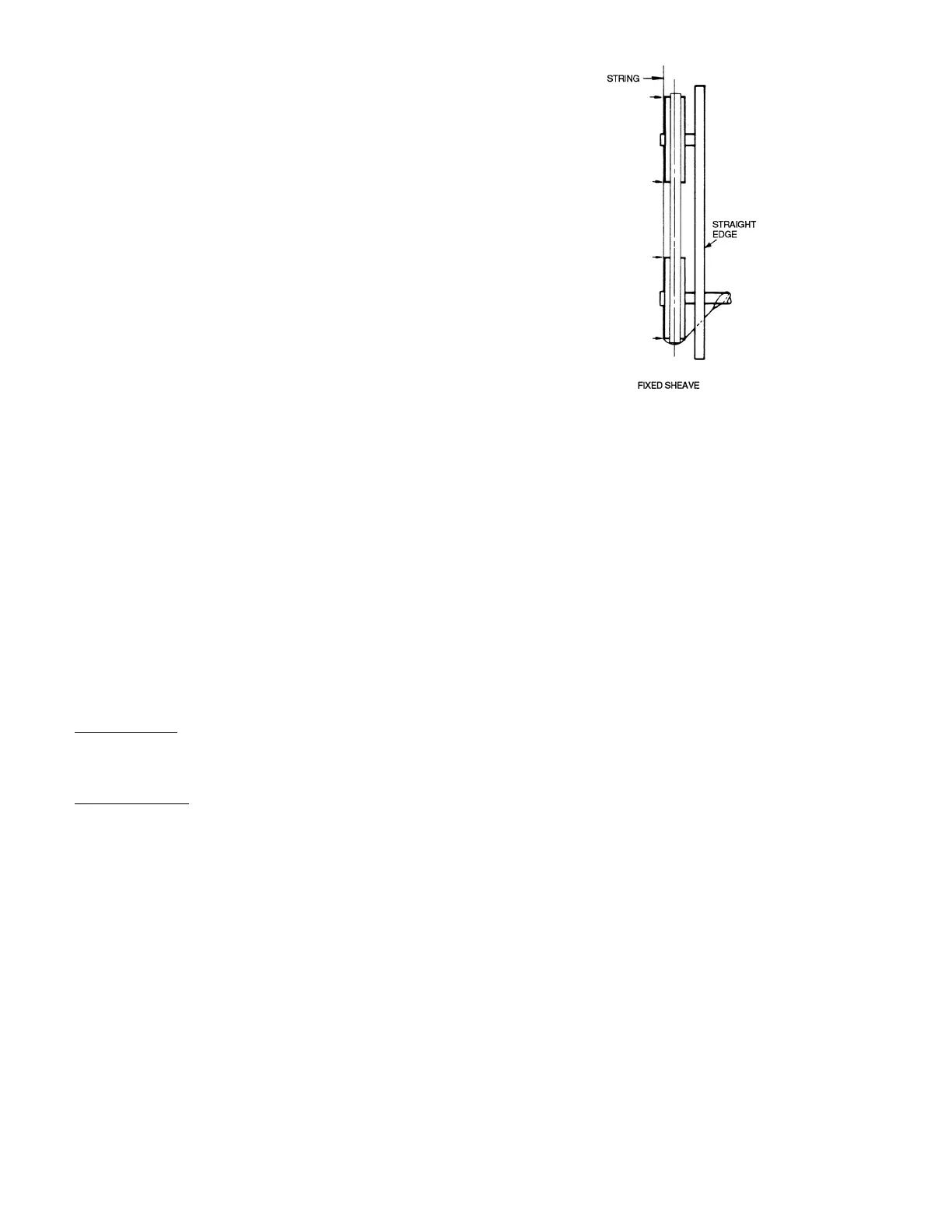
1. To check the location of the fixed sheaves on the shafts, use a
straightedge or a piece of string. If the sheaves are properly
aligned, the string will touch them at the points indicated by
the arrows in Fig. 87. Rotate each sheave a half revolution to
determine whether the sheave is wobbly or the drive shaft is
bent. Correct any misalignment.
2. With sheaves aligned, tighten cap screws evenly and
progressively.
NOTE: There should be a
1
/
8
-in. to
1
/
4
-in. gap between the
mating part hub and the bushing flange. If the gap is closed,
the bushing is probably the wrong size.
3. With taper-lock bushed hubs, be sure the bushing bolts are
tightened evenly to prevent side-to-side pulley wobble.
Check by rotating sheaves and rechecking sheave alignment.
When substituting field-supplied sheaves for factory-supplied
sheaves, only the motor sheave should be changed.
Fig. 87 — Sheave Alignment
Evaporator Fan Performance Adjustment
To change fan speeds from factory settings:
1. Shut off unit power supply.
2. Loosen nuts on the 4 carriage bolts in the mounting base.
Using adjusting bolts and plate, slide the motor and remove
the belt.
3. Loosen movable-pulley flange setscrew.
4. Screw the movable flange toward the fixed flange to increase
speed, and away from the fixed flange to decrease speed.
Increasing the fan speed increases the load on the motor. Do
not exceed the maximum speed specified in Tables 2 and 4.
5. Set the movable flange at nearest keyway of the pulley hub
and tighten the setscrew. (See Tables 2 and 4 for speed
change for each full turn of pulley flange.)
6. Replace and tighten the belts (see Belt Tension Adjustment
section).
7. Restore power to the unit.
To align fan and motor pulleys:
1. Loosen fan pulley setscrews.
2. Slide fan pulley along fan shaft.
3. Make angular alignment by loosening motor from mounting
plate.
4. Restore power to unit.
BELT TENSION ADJUSTMENT
Using a gage, apply 4 lb of force to the center of the belt and adjust
the tension until a deflection of
1
/
64
-in. is achieved for every inch
of shaft center distance. See Fig. 88.
Ideal belt tension is the lowest value under which belt slip will not
occur at peak load conditions.
 Loading...