Do you have a question about the Carrier PAD324 and is the answer not in the manual?
Defines DANGER, WARNING, CAUTION, and NOTE signal words for hazard communication.
Explains how signal words are used in manuals and on product labels for hazard identification.
Covers electrical shock, refrigerant pressure, environmental release, and sharp metal hazards.
Brief overview of the PAD3 unit design and capabilities.
Steps for checking unit identification and inspecting for shipping damage.
Guidelines for unit placement, clearances, and ductwork fabrication.
Safety precautions for rigging, lifting, and potential falling hazards.
Critical warnings about unit falling hazards and property damage during rigging operations.
Details dimensions, center of gravity, and corner weights for PAD3 2-3 Ton units.
Specifies minimum clearances for combustible materials and NEC requirements.
Details dimensions, center of gravity, and corner weights for PAD3 3.5-5 Ton units.
Specifies minimum clearances for combustible materials and NEC requirements.
Illustrates roof curb construction, dimensions, and unit placement guidelines.
Provides rigging weights and important safety notices for riggers.
Instructions for condensate disposal and a diagram of the condensate trap setup.
Emphasizes disconnecting power before servicing electrical components.
Steps for converting unit for downflow discharge and duct opening details.
Warns of electrical hazards and potential unit damage from improper wiring.
Steps for high-voltage connections and control wiring guidelines.
Refers to diagrams for connections and outlines 208-V operation procedures.
Information on transformer protection and overload troubleshooting.
Guidance on installing accessory electric heaters.
Covers fire, explosion, and electrical shock hazards during pre-start-up procedures.
Procedures for checking, repairing, and charging the refrigerant system.
Steps for starting the cooling section, verifying controls, and adjusting refrigerant charge.
Discusses airflow recommendations and hazards of improper operation.
Instructions for setting single or dual cooling fan speeds, including dehumidification.
Diagram of IFB and color coding for indoor fan motor leads.
Explains continuous fan operation and the cooling sequence of operation.
Critical warning to disconnect power before servicing to prevent injury or death.
Critical warning to disconnect power before servicing to prevent injury or death.
Critical warning to disconnect power before servicing to prevent injury or death.
Critical warning to disconnect power before servicing to prevent injury or death.
Critical warning to disconnect power before servicing to prevent injury or death.
Warns of personal injury, unit damage, and electrical hazards during maintenance.
Guidelines for maintaining air filters, blower motor, and indoor coil.
Procedures for fan blade positioning, coil cleaning, and drain pan inspection.
Annual inspection of electrical controls, wiring, and refrigerant circuit for leaks.
Details R-410A safety, pressure, explosion risks, and handling precautions.
Information on evaporator airflow, metering devices, pressure switches, and compressor.
Precautions for working on roofs and handling R-410A refrigerant and components.
Directs users to troubleshooting charts and start-up checklists.
Key safety and servicing notes specific to R-410A air conditioners.
Troubleshooting steps for compressor and fan operational failures.
Diagnosing problems related to head pressure, suction pressure, and compressor cycling.
Recording unit details and verifying pre-start-up conditions.
Checklist items for electrical supply, compressor/fan amps, and refrigerant pressures.
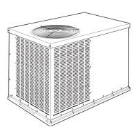
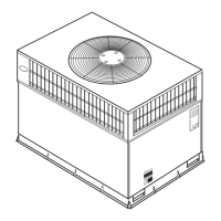
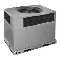
This document provides installation and maintenance instructions for the R-410A Single Package Electric Cooling unit, models PAD324-60 (1 & 3 Phase). These units are fully self-contained and designed for outdoor installation, suitable for either rooftop or ground-level cement slab mounting. They feature discharge openings for both horizontal and downflow duct configurations, with downflow openings covered at the factory.
The R-410A Single Package Electric Cooling unit is designed to provide cooling for residential and non-residential applications. It integrates a compressor, condenser, evaporator, and fan components into a single outdoor unit. The unit can be configured for single-speed cooling or two-speed cooling with an enhanced dehumidification feature, depending on the thermostat or dehumidistat used. It also supports the installation of accessory electric heaters for heating functionality.
The manual provides detailed physical data for various unit sizes (24, 30, 36, 42, 48, 60), including:
The unit requires a separate electrical service with a field-supplied, waterproof disconnect switch. High-voltage connections are made to the compressor contactor, and low-voltage connections (no. 18 AWG or no. 16 AWG for runs over 100 ft) are made to the thermostat and indoor fan board. Three-phase scroll compressors are direction-oriented and require correct 3-phase power lead orientation for proper operation.
| Brand | Carrier |
|---|---|
| Model | PAD324 |
| Category | Air Conditioner |
| Language | English |