12 Specifications subject to change without notice. IM-40MBDQ-05
CONDENSATE DRAIN AND CONDENSATE
LIFT PUMP INSTALLATION (HORIZONTAL
INSTALLATION)
For sizes 9, 12 and 18, the condensate lift pump is provided in
a separate box. Use the following steps to install the External
Condensate Lift Pump for a horizontal installation of the
indoor unit.
NOTE: Drain connections A, B and C are covered with caps.
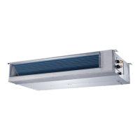
1. For sizes 09K and 12K:
a. Remove the cap on the drainage outlet.
b. Cut both ends of the rubber tubing provided into a straight
one.
c. Connect the drainage outlet and condensate lift pump using
the rubber tubing and secure it with clamps on both ends
(see Fig. 30).
d. Plug the power cable of the external pump to CN13 /
“PUMP” pin and plug the water level sensor cable to the
CN5 / “WATER” to enable the pump (see Fig. 34).
2. For size 18K:
a. R
emove the cap on drain connector B.
b. Connect drain connector B and the condensate lift pump
using the L rubber hose and secure it with clamps on both
ends.
c. Connect the drainpipe to connector D (see Fig. 31).
d. Plug the power cable of the external pump to CN13 /
“PUMP” pin and plug the water level sensor cable to CN5 /
“WATER” to enable the pump (see Fig. 34).
Fig. 30 — Condensate lift pump installation sizes 09K−12K
Fig. 31 — Condensate lift pump installation size 18K
3.
Sizes 24K, 36K, 48K and 58K have a built-in condensate lift pump
.
Drain connections (A, B and C) are covered with caps.
Connect the drainpipe to connector D (see Fig. 32).
Fig. 32 — Connection of drain pipe to condensate lift pump sizes 24-58K
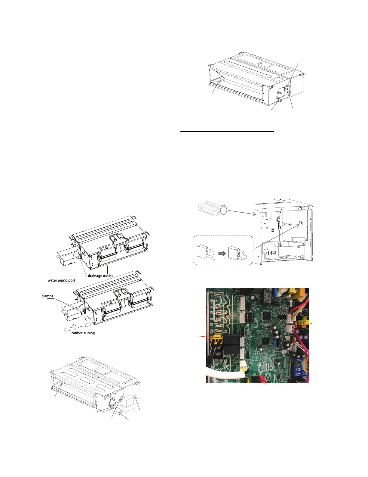
Disabling the Condensate Lift Pump
The pump must be disabled while the unit is installed
vertically (upflow) or the lift pump assembly is removed
from its original position:
• Open the Control Box assembly cover, unplug the “CN13 PUMP”
pin to disable the pump function, and short-connect the “CN5
WATER” plug to disable the water level sensor by either splicing the
wires coming out of the CN5 WATER plug or by using a jumper plug
Replacement Component part number 17401204000333 (optional in
some units otherwise sold separately) (see Figures 33 and 34).
Fig. 33 — Disable condensate lift pump
Fig. 34 — Condensate Lift Pump Connectors
Remove
the cover
Short connect the “CN5” water
Unplug the CN13 “PUMP” plug pin
 Loading...