35
APPENDIX D
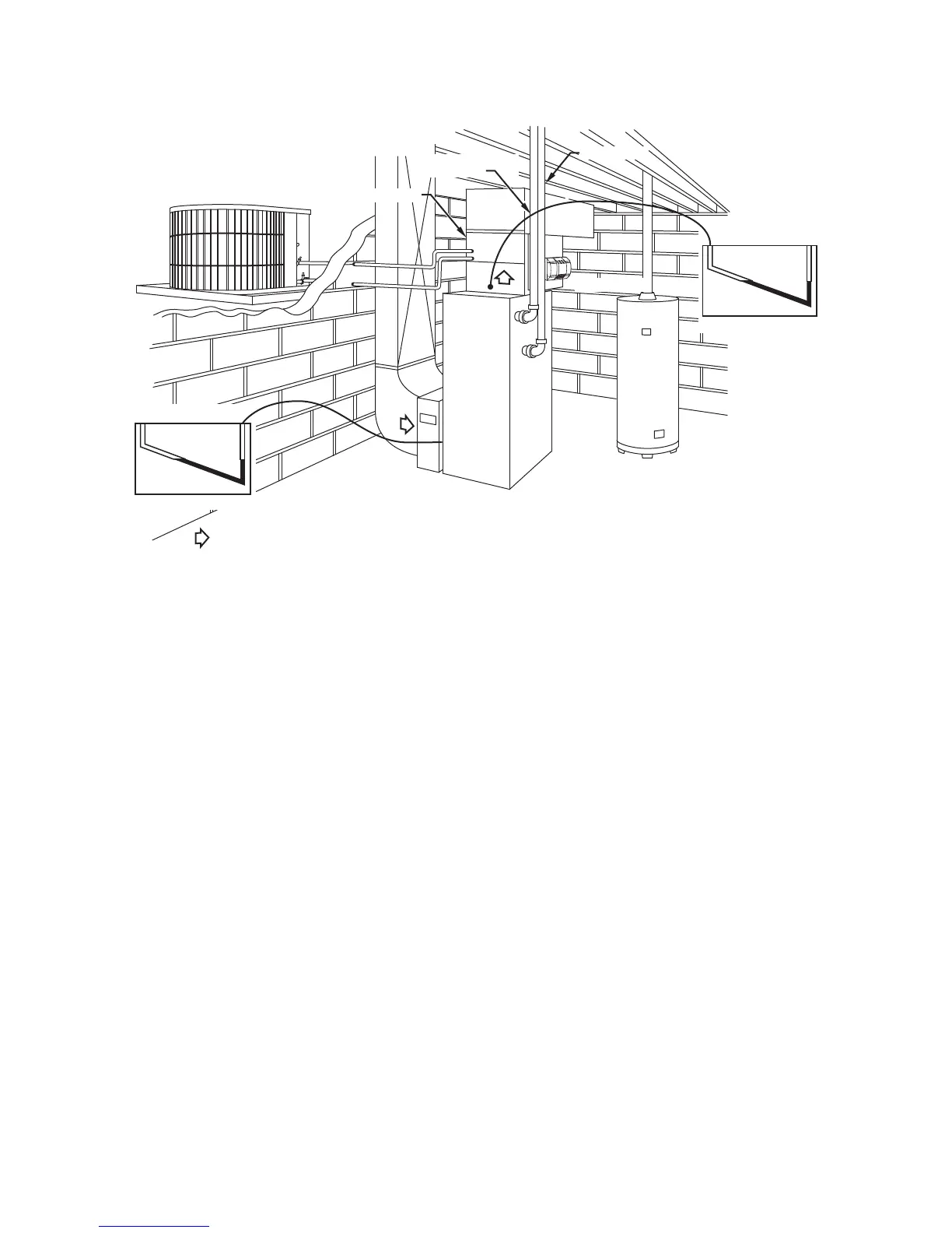
STATIC PRESSURE READING LOCATION DIAGRAMS
COMBUSTION
AIR PIPE
A/C COIL
OUTDOOR UNIT
VENT PIPE
HUMIDIFIER
GAS-FIRED
WATER HEATER
ELECTRONIC
AIR CLEANER
AIRFLOW
SUPPLY STATIC
INCLINE MANOMETER
RETURN STATIC
INCLINE MANOMETER
A03091
Fig. 5 -- Upflow Total Static Pressure Reading Locations
Tools Needed:
1.
Pitot Tube
2.
Incline Manometer/Magnahelic
Example 1:
Return ESP after Filter
0.20 in.w.c.
Supply ESP before Coil
0.40 in.w.c.
-- -- -- -- -- -- -- -- -- -- -- -- -- -- -- -- -- -- -- -- -- -- -- -- -- -- -- -- -- -- -- -- -- -- -- -- -- -- -- -- -- -- -- -- -- -- -- -- -- -- -- -- -- --
Total ESP
0.60 in.w.c.
Example 2:
Return ESP before Filter
0.10 in.w.c.
Filter Static Pressure Drop @ 2000 cfm 0.10 in.w.c.
Supply ESP after Coil
0.20 in.w.c.
Coil Static Pressure Drop Wet
0.20 in.w.c.
-- -- -- -- -- -- -- -- -- -- -- -- -- -- -- -- -- -- -- -- -- -- -- -- -- -- -- -- -- -- -- -- -- -- -- -- -- -- -- -- -- -- -- -- -- -- -- -- -- -- -- -- -- --
Total ESP
0.60 in.w.c.
Both Examples 1 and 2 are correct. Example 1 ESP readings were taken as laid out in static pressure reading location diagrams (Fig. 5).
Example 2 readings are taken as described. The coil and filter static pressure drops were taken from the manufacturer’s product data sheets
with the assumption that 2000 cfm is being delivered.