EasyManua.ls Logo

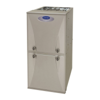
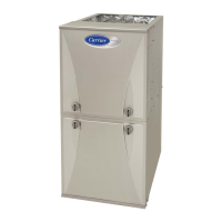
Carrier PG92MSAA36060A User Manual

Carrier PG92MSAA36060A
72 pages
To Next Page IconTo Next Page
Page #1 background imageLoading...
Page #1 background image
Installation, Start-up, Operating and
Service and Maintenance Instructions
NOTE: Read the entire instruction manual before starting the
installation.
TABLE OF CONTENTS
REQUIRED NOTICE FOR MASSACHUSETTS INSTALLATIONS
IMPORTANT . . . . . . . . . . . . . . . . . . . . . . . . . . . . . . . . . . . . . . . . . . . 2
Table 1 – Dimensions . . . . . . . . . . . . . . . . . . . . . . . . . . . . . . . . . . 3
SAFETY CONSIDERATIONS . . . . . . . . . . . . . . . . . . . . . . . . . . . . . 3
Table 2 – Minimum Clearances to Combustible Materials
for All Units . . . . . . . . . . . . . . . . . . . . . . . . . . . . . . . . . . . . . . . . . . 5
INTRODUCTION . . . . . . . . . . . . . . . . . . . . . . . . . . . . . . . . . . . . . . . 5
Table 3 – Loose Parts Bag . . . . . . . . . . . . . . . . . . . . . . . . . . . . . . . 6
CODES AND STANDARDS. . . . . . . . . . . . . . . . . . . . . . . . . . . . . . . 6
ELECTROSTATIC DISCHARGE (ESD) PRECAUTIONS PROCE-
DURE . . . . . . . . . . . . . . . . . . . . . . . . . . . . . . . . . . . . . . . . . . . . . . . . . 7
ACCESSORIES . . . . . . . . . . . . . . . . . . . . . . . . . . . . . . . . . . . . . . . . . 7
LOCATION . . . . . . . . . . . . . . . . . . . . . . . . . . . . . . . . . . . . . . . . . . . . 7
AIR FOR COMBUSTION AND VENTILATION . . . . . . . . . . . . . . 8
Table 4 – Minimum Free Area Required for Each Combustion Air
Opening or Duct to Outdoors. . . . . . . . . . . . . . . . . . . . . . . . . . . . . 9
Table 5 – Minimum Space Volumes for 100% Combustion, Ventila-
tion and Dilution Air from Outdoors . . . . . . . . . . . . . . . . . . . . . . . 9
CONDENSATE TRAP. . . . . . . . . . . . . . . . . . . . . . . . . . . . . . . . . . . 11
CONDENSATE DRAIN CONNECTION . . . . . . . . . . . . . . . . . . . . 13
INSTALLATION . . . . . . . . . . . . . . . . . . . . . . . . . . . . . . . . . . . . . . . 15
Table 6 – Opening Dimensions - In. (mm) . . . . . . . . . . . . . . . . . 18
FILTER ARRANGEMENT . . . . . . . . . . . . . . . . . . . . . . . . . . . . . . . 19
Table 7 Filter Media Pressure Drop (Clean) Versus Airflow - in. w.c.
(Pa) . . . . . . . . . . . . . . . . . . . . . . . . . . . . . . . . . . . . . . . . . . . . . . . . 19
Table 8 – Filter Media Pressure Drop (Clean) Versus Face Velocity-
in. w.c. (Pa) . . . . . . . . . . . . . . . . . . . . . . . . . . . . . . . . . . . . . . . . . 20
Table 9 – Air Filter Selection and Duct Sizing - In. (mm) . . . . . 20
AIR DUCTS . . . . . . . . . . . . . . . . . . . . . . . . . . . . . . . . . . . . . . . . . . . 22
GAS PIPING. . . . . . . . . . . . . . . . . . . . . . . . . . . . . . . . . . . . . . . . . . . 23
Table 10 – Maximum Capacity of Pipe . . . . . . . . . . . . . . . . . . . . 23
ELECTRICAL CONNECTIONS. . . . . . . . . . . . . . . . . . . . . . . . . . . 24
Table 11 – Electrical Data . . . . . . . . . . . . . . . . . . . . . . . . . . . . . . 25
ACCESS0RIES. . . . . . . . . . . . . . . . . . . . . . . . . . . . . . . . . . . . . . . . . 27
VENTING. . . . . . . . . . . . . . . . . . . . . . . . . . . . . . . . . . . . . . . . . . . . . 29
Table 12 – Vent Termination Kit for Direct Vent (2-pipe) Systems30
Table 13 – Approved Combustion-Air and Vent Pipe, Fitting and Ce-
ment Materials . . . . . . . . . . . . . . . . . . . . . . . . . . . . . . . . . . . . . . . 30
Table 14 – Maximum Equivalent Vent Length . . . . . . . . . . . . . . 39
Table 15 – Deductions from Maximum Equivalent Vent Length - Ft.
(M) . . . . . . . . . . . . . . . . . . . . . . . . . . . . . . . . . . . . . . . . . . . . . . . . 40
Table 16 – Maximum Allowable Exposed Vent Lengths in Uncondi-
tioned Space Table - Ft. . . . . . . . . . . . . . . . . . . . . . . . . . . . . . . . . 43
Table 17 – Hanger Spacing . . . . . . . . . . . . . . . . . . . . . . . . . . . . . 45
AIR DELIVERY - CFM. . . . . . . . . . . . . . . . . . . . . . . . . . . . . . . . . . 48
Table 18 – Air Delivery - CFM (with filter) . . . . . . . . . . . . . . . . 48
Table 19 – Airflow Settings. . . . . . . . . . . . . . . . . . . . . . . . . . . . . 50
FURNACE CONTROL PROGRAMMING AND NAVIGATION 50
Table 20 – System Status Display Codes . . . . . . . . . . . . . . . . . . 50
Table 21 – Main Menu Options. . . . . . . . . . . . . . . . . . . . . . . . . . 51
SERVICE LABEL . . . . . . . . . . . . . . . . . . . . . . . . . . . . . . . . . . . . . . 52
START-UP, ADJUSTMENT, AND SAFETY CHECK . . . . . . . . . 53
Table 22 – Test Sequence . . . . . . . . . . . . . . . . . . . . . . . . . . . . . . 53
WIRING DIAGRAM . . . . . . . . . . . . . . . . . . . . . . . . . . . . . . . . . . . . 54
ADJUSTMENTS . . . . . . . . . . . . . . . . . . . . . . . . . . . . . . . . . . . . . . . 55
Table 23 – Altitude Derate Multiplier for U.S.A. . . . . . . . . . . . . 55
Table 24 – Gas Rate (CU ft./hr). . . . . . . . . . . . . . . . . . . . . . . . . . 57
Table 25 – Orifice Size and Manifold Pressure (in. w.c.) for Gas Input
Rate . . . . . . . . . . . . . . . . . . . . . . . . . . . . . . . . . . . . . . . . . . . . . . . 57
SERVICE AND MAINTENANCE PROCEDURES. . . . . . . . . . . . 59
CARE AND MAINTENANCE . . . . . . . . . . . . . . . . . . . . . . . . . . . . 60
WINTERIZATION. . . . . . . . . . . . . . . . . . . . . . . . . . . . . . . . . . . . . . 65
SEQUENCE OF OPERATION . . . . . . . . . . . . . . . . . . . . . . . . . . . . 65
TROUBLESHOOTING . . . . . . . . . . . . . . . . . . . . . . . . . . . . . . . . . . 67
PARTS REPLACEMENT INFORMATION GUIDE . . . . . . . . . . . 71
MODEL NOMENCLATURE . . . . . . . . . . . . . . . . . . . . . . . . . . . . . 71
To learn more about this appliance and installation via a mobile device,
go to https://www.CAC/BDP.com/NFC or use the QR code below. To
access airflow tables or troubleshooting guide on your mobile device go
to mlctraining.com/training/techdocs/40/ or use the QR code below.
A220943
A200352
Portions of the text and tables are reprinted from NFPA 54/ANSI Z223.1E, with permission of National Fire Protection Association, Quincy, MA
02269 and American Gas Association, Washington DC 20001. This reprinted material is not the complete and official position of the NFPA or ANSI
on the referenced subject, which is represented only by the standard in its entirety.
PG92MSA
Single-Stage, 35-in. (889 mm) Tall, 4-Way Multipoise
High Efficiency Condensing Gas Furnace
Question and Answer IconNeed help?

Do you have a question about the Carrier PG92MSAA36060A and is the answer not in the manual?

Carrier PG92MSAA36060A Specifications

General IconGeneral
ModelPG92MSAA36060A
TypeGas Furnace
Heating Capacity60, 000 BTU
Fuel TypeNatural Gas
AFUE92%
Heating StagesTwo-Stage
BTU Input60, 000
BrandCarrier
Model NumberPG92MSAA36060A
Input BTU60, 000 BTU
Output BTU55, 200 BTU
Stages2
Ignition TypeHot Surface Ignition
Heat Exchanger MaterialStainless Steel
Efficiency Rating92% AFUE
Warranty10 Years

Summary

REQUIRED NOTICE FOR MASSACHUSETTS INSTALLATIONS

INSTALLATION OF CARBON MONOXIDE DETECTORS

Specifies requirements for CO detector installation for side wall vented gas equipment.

APPROVED CARBON MONOXIDE DETECTORS

Details standards CO detectors must meet (NFPA 720, ANSI/UL 2034).

SAFETY CONSIDERATIONS

CARBON MONOXIDE POISONING HAZARD

Warns about CO poisoning, emphasizing installation, maintenance, and service instructions.

WARNINGS AND CAUTIONS

PERSONAL INJURY AND PROPERTY DAMAGE HAZARD

Warns against using non-manufacturer approved parts and accessories for safety and reliability.

FIRE, INJURY, OR DEATH HAZARD

Warns against bypassing safety controls like limit switches or thermal switches.

AIR FOR COMBUSTION AND VENTILATION

Ventilated Combustion Air Applications (for U.S. Only)

Details requirements for ventilated combustion air applications.

CODES AND STANDARDS

Safety

Lists US and Canadian safety codes applicable to furnace installation.

Combustion and Ventilation Air

Specifies codes related to combustion and ventilation air requirements.

ELECTROSTATIC DISCHARGE (ESD) PRECAUTIONS PROCEDURE

FURNACE CORROSION HAZARD

PERSONAL INJURY AND/OR PROPERTY DAMAGE HAZARD

Warns about improper use or installation leading to premature component failure.

CARBON MONOXIDE POISONING HAZARD

Outdoor Combustion Air Method

Details requirements for providing outdoor air for combustion, ventilation, and dilution.

Indoor Combustion Air NFPA & AGA

CONDENSATE TRAP

Condensate Trap - Upflow Orientation

Explains that the condensate trap does not need relocation for upflow orientation.

Condensate Trap - Downflow Orientation

Details how to relocate the condensate trap for downflow installation.

Condensate Trap - Horizontal Orientation

CONDENSATE DRAIN CONNECTION

PROPERTY DAMAGE HAZARD

Warns that plugged drains or failed pumps can cause furnace shutdown.

For Left Side Condensate Drain Connection

Supply Air Connections

Return Air Connections

FILTER ARRANGEMENT

FIRE, CARBON MONOXIDE AND POISONING HAZARD

Warns against operating without a filter or with access doors removed.

Filter and Return Duct Sizing

Filter and Return Duct Sizing (continued)

Roll-Out Protection

AIR DUCTS

GAS PIPING

GAS PIPING (continued)

ELECTRICAL CONNECTIONS

ELECTRICAL CONNECTIONS (continued)

FIRE HAZARD

Warns against using aluminum wire for electrical connections to the furnace.

115-V Wiring

J-Box Installation

FIRE OR ELECTRICAL SHOCK HAZARD

Warns about high voltage field connections and proper use of J-box or external box.

External Electrical Box on Furnace Casing

J-Box Installation (continued)

WARNING

FIRE, EXPLOSION, ELECTRICAL SHOCK, AND CARBON MONOXIDE POISONING HAZARD

General safety warnings for wiring and control routing.

FIRE, EXPLOSION, ELECTRICAL SHOCK AND CARBON MONOXIDE POISONING HAZARD

General safety warnings regarding modification of the product.

24-V Wiring

VENTING

Direct Vent / 2-Pipe System

Describes requirements for direct-vent systems where air is taken from outdoors.

Ventilated Combustion Air Systems

Details requirements for ventilated combustion air systems, including termination and air supply.

Non-Direct Vent (1-pipe) System

Describes requirements for non-direct vent systems where air is taken from adjacent areas.

MATERIALS

Inside Corner Terminations

Inside Corner Terminations (continued)

Direct Vent / 2-Pipe System

Non-Direct Vent / 1-Pipe System

Size the Vent and Combustion Air Pipes

ADDITIONAL INFORMATION FOR POLYPROPYLENE VENTING SYSTEMS

Venting System Length Calculations

Explains how to calculate Total Equivalent Vent Length (TEVL) considering pipe length and fittings.

Venting System Length Calculations (continued)

Installing the Vent Pipe Adapter and Combustion Air Pipe Adapter

Installing the Vent Termination

Two-Pipe and Single-Pipe Terminations

Inducer Outlet Restrictor

Venting System Length Calculations

AIR DELIVERY - CFM

AIR DELIVERY - CFM (continued)

FURNACE CONTROL PROGRAMMING AND NAVIGATION

Section on furnace control programming and navigation.

On-Board Control Method

Introduces the furnace control's LCD display and pushbutton interface for adjustments.

FURNACE CONTROL PROGRAMMING AND NAVIGATION (continued)

On-Board Control Method (continued)

Explains how to navigate the control menu and adjust parameters.

ELECTRICAL SHOCK HAZARD

Warns about hazards when accessing the furnace control.

FURNACE OVERHEATING HAZARD

SERVICE LABEL

START-UP, ADJUSTMENT, AND SAFETY CHECK

UNIT OPERATION HAZARD

Warns against improper operation or failure to reset the limit switch.

IMPORTANT INSTALLATION AND START-UP PROCEDURES

Lists critical steps to follow for proper installation and start-up to avoid issues.

WIRING DIAGRAM

Prime Condensate Trap with Water

CARBON MONOXIDE POISONING HAZARD

Warns about CO poisoning from improperly configured or unprimed condensate traps.

ADJUSTMENTS

FURNACE DAMAGE HAZARD

Cautions against redrilling orifices, as it can cause noise and heat exchanger damage.

Check Inlet Gas Pressure

Adjust Manifold Pressure

Adjust Temperature Rise

FIRE HAZARD

Warns about tightening the set screw and installing the pipe plug to prevent gas leaks.

FURNACE OVERHEATING HAZARD

Advises rechecking temperature rise and recommended operation points.

Check Safety Controls

Check Main Limit Switch

Details how to test the main limit switch for proper operation during overheat conditions.

Check Pressure Switch(es)

Explains how to test the pressure switch for proper draft inducer blower operation.

SERVICE AND MAINTENANCE PROCEDURES

ELECTRICAL CONTROLS AND WIRING

Covers electrical controls and wiring.

ELECTRICAL OPERATION HAZARD

Warns about electrical hazards during servicing and the importance of proper grounding.

Retrieving Stored Fault Codes

CARE AND MAINTENANCE

FIRE OR EXPLOSION HAZARD

Warns about storing flammable materials near the furnace.

CARBON MONOXIDE POISONING AND FIRE HAZARD

Warns against operating without a filter or with access doors removed.

Cleaning and/or Replacing Air Filter

Details how to clean or replace the furnace air filter.

Blower Motor and Wheel Maintenance

Cleaning Burners and Flame Sensor

Cleaning Burners and Flame Sensor (continued)

Servicing Hot Surface Igniter

Flushing Collector Box and Drainage System

ELECTRICAL SHOCK AND FIRE HAZARD

Warns to turn off gas and electrical supplies and use lockout tags before servicing.

Cleaning Condensate Drain and Trap

Cleaning Heat Exchangers

Primary Heat Exchangers

Explains how to clean primary heat exchangers and when replacement is necessary.

WARNING

Warning section.

ELECTRICAL SHOCK, FIRE OR EXPLOSION HAZARD

Warns to turn off gas and electrical supplies and use lockout tags before maintenance.

WINTERIZATION

UNIT AND PROPERTY DAMAGE HAZARD

Warns about potential unit or property damage if furnace is not winterized in cold spaces.

UNIT COMPONENT DAMAGE HAZARD

Cautions against using automotive antifreeze, which can damage plastic components.

SEQUENCE OF OPERATION

Troubleshooting

GAS FURNACE CHECKLIST

Gas Adjustment

Section for recording gas adjustment parameters like heat content, specific gravity, and manifold pressure.

FIRING RATE:

Details how to calculate or find the furnace firing rate based on gas properties.

PARTS REPLACEMENT INFORMATION GUIDE

Related product manuals