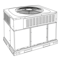
PGD4, PGS4, Series G, H WPG4 Series D, H Ultra Low NOx: Installation Instructions
Manufacturer reserves the right to change, at any time, specifications and designs without notice and without obligations.
29
60090
35 - 65
(19 - 36)
Low
†
Blue
CFM
839 768 697 625 551 486 422 360 306 x
BHP 0.09 0.10 0.10 0.11 0.12 0.12 0.13 0.14 0.14 x
Gas Heat Rise (°F) NA NA NA NA NA NA NA NA NA NA
Gas Heat Rise (°C) NA NA NA NA NA NA NA NA NA NA
Med-Low
**
Pink Heating
CFM
1403 1361 1320 1276 1236 1192 1145 1099 1054 1012
BHP 0.28 0.29 0.30 0.31 0.31 0.33 0.34 0.35 0.36 0.37
Gas Heat Rise (°F) 48 50 51 53 55 57 59 62 64 NA
Gas Heat Rise (°C) 27 28 28 29 30 32 33 34 36 NA
Medium
‡
Red
Cooling
Alternate Heating
CFM
1822 1788 1757 1726 1690 1657 1623 1589 1553 1518
BHP 0.54 0.55 0.56 0.57 0.59 0.60 0.61 0.62 0.63 0.64
Gas Heat Rise (°F) 37 38 39 39 40 41 42 43 44 45
Gas Heat Rise (°C) 21 21 21 22 22 23 23 24 24 25
Med-High Orange Alternate Cooling
CFM
1982 1940 1900 1859 1816 1775 1739 1701 1655 1596
BHP 0.61 0.62 0.63 0.65 0.66 0.67 0.69 0.70 0.71 0.73
Gas Heat Rise (°F) NA NA NA NA NA NA NA NA NA NA
Gas Heat Rise (°C) NA NA NA NA NA NA NA NA NA NA
High Black High Static Cooling Only
CFM
2271 2241 2206 2171 2134 2080 1973 1857 1746 1596
BHP 0.90 0.91 0.93 0.95 0.96 0.95 0.90 0.84 0.78 0.73
Shaded areas indicate speed/static combinations that are not permitted for dehumidification speed.
*. Air delivery values are without air filter and are for dry coil (See Wet Coil Pressure Drop table).
†. Factory-shipped continuous fan speed
‡. Factory-shipped cooling speed
**. Factory-shipped heating speed
Table 9 – Dry Coil Air Delivery
*
- Horizontal and Downflow Discharge Sizes 24-60 208/230VAC - 1 & 3 Phase (Continued)
Unit Size
Heating Rise
°F (°C)
Motor Speed Tap
Allowable
Functions
ESP (in. W.C.)
0.1 0.2 0.3 0.4 0.5 0.6 0.7 0.8 0.9 1
Table 10 – Wet Coil Pressure Drop (IN. W.C.)
Unit
Size
Standard CFM (SCFM)
600 700 800 900 1000 1100 1200 1300 1400 1500 1600 1700 1800 1900 2000 2100 2200
24 0.03 0.04 0.04 0.05 0.06
30 0.05 0.06 0.07 0.08 0.11
36 0.06 0.06 0.09 0.10 0.11 0.14
42 0.05 0.05 0.06 0.07 0.08 0.08 0.09 0.09 0.11
48 0.04 0.06 0.09 0.10 0.10 0.11 0.12 0.13 0.14
60 0.06 0.07 0.01 0.08 0.09 0.10 0.12 0.13
Table 11 – Economizer with 1-in. Filter Pressure Drop (IN. W.C.)
Filter Size in. (mm)
Cooling
Tons
Standard CFM (SCFM)
600 700 800 900 1000 1100 1200 1300 1400 1500 1600 1700 1800 1900 2000 2100 2200
600-1400 CFM
12x20x1+12x20x1
(305x508x25+305x508x25)
2.0,
2.5,
3.0
- - 0.09 0.14 0.16 0.18 0.25 0.28 0.30 - - - - - - - -
1200-1800 CFM
16x24x1+14x24x1
(406x610x25+356x610x25)
3.5,
4.0
- - - - - - 0.10 0.11 0.12 0.13 0.14 0.16 0.16 - - - -
1500-2200 CFM
16x24x1+18x24x1
(406x610x25+457x610x25)
5.0 - - - - - - - - - 0.15 0.17 0.18 0.20 0.21 0.22 0.23 0.23
 Loading...
