EasyManua.ls Logo

Carrier Residential Air Conditioners and Heat Pumps User Manual

Carrier Residential Air Conditioners and Heat Pumps
64 pages
To Next Page IconTo Next Page
Page #1 background imageLoading...
Page #1 background image
Application Guideline
and Service Manual
Resident ial Air Conditio ner s and Heat Pumps
U s i n g R --- 2 2 a n d P u r o n r Refrigerant
TABLE OF CONTENTS
PAGE
UNIT IDENTIFICATION 2.............................
SAFETY CONSIDERATIONS 3.........................
INTRODUCTION 3...................................
INSTALLATION GUIDELINE 3........................
ACCESSORIES AND DESCRIPTIONS 4 -- 5..............
LOW--AMBIENT GUIDELINE 6 -- 7......................
LONG LINE GUIDELINE 8............................
CABINET ASSEMBLY & COMPONENTS 8 -- 11...........
ELECTRICAL 12 -- 13.................................
Aluminum Wire 12.................................
Contactor 12......................................
Capacitor 12--13...................................
Cycle Protector 13..................................
Crankcase Heater 13................................
Time--Delay Relay 13...............................
PRESSURE SWITCHES 14.............................
DEFROST THERMOSTAT 15..........................
DEFROST CONTROL BOARD 15 -- 17...................
SYSTEM FUNCTION AND
SEQUENCE OF OPERATION 17--18.....................
COPELAND SCROLL COMPRESSOR 19................
LG SCROLL COMPRESSOR 19--20.....................
COMPRESSOR TROUBLESHOOTING 21--23.............
Compressor Failures 21..............................
Mechanical Failures 21--22...........................
Electrical Failures 23................................
REFRIGERATION SYSTEM 24--31......................
Refrigerant 24.....................................
Servicing Systems on Roofs With Synthetic Materials 24....
Brazing 24........................................
Service Valves and Pump down 25--27..................
Liquid Line Filter Drier 28...........................
Suction Line Filter Drier 28...........................
Accumulator 29....................................
Thermostatic Expansion Valve (TXV) 30--31.............
MAKE PIPING CONNECTIONS 31......................
PAGE
REFRIGERATION SYSTEM REPAIR 32--34...............
Leak Detection 32..................................
Coil Removal 32...................................
Compressor Removal and Replacement 33...............
System Clean--Up After Burnout 33....................
Evacuation 34.....................................
CHECK CHARGE 34..................................
TROUBLESHOOTING WITH SUPERHEAT 35-- 44..........
TWO--STAGE 25HNB / 24ANB 45--55...................
APPLICATION GUIDELINES 45........................
MODEL PLUG 45....................................
Airflow Selections For 24ANB7 / 25HNB6 / 24ANB1 /25HNB9
Using Non--Communicating (Non--infinity) Thermostats 46.....
Airflow Selection For FV4 Fan Coils For 24ANB1, 24ANB7,
25HNB6, 25HNB9 Using Non--Communicating (non--Infinity)
Thermostats 46.......................................
GENERAL INFORMATION 46--47.......................
CHECK CHARGE 47--48...............................
SYSTEM FUNCTION AND
SEQUENCE OF OPERATION 48--51.....................
TROUBLESHOOTING 51--55...........................
TWO STAGE NON--COMMUNICATING
24ACB7 / 25HCB6 56--58..............................
OPERATING AMBIENT 56.............................
Airflow Selections (ECM Furnaces) 56.....................
Airflow Selection for Variable Speed Furnaces
(non--communicating) 56................................
Airflow Selection for FV4C Fan Coils
(non--communicating) 56................................
SYSTEM FUNCTION AND
SEQUENCE OF OPERATION 57--58.....................
CHECK CHARGE 58..................................
CARE AND MAINTENANCE 59--60.....................
PURON QUICK REFERENCE GUIDE 60.................
AC TROUBLESHOOTING CHART 61....................
HP TROUBLESHOOTING CHART -- HEATING CYCLE 62..
HP TROUBLESHOOTING CHART -- COOLING CYCLE 63..
INDEX OF TABLES 64................................

Table of Contents

Question and Answer IconNeed help?

Do you have a question about the Carrier Residential Air Conditioners and Heat Pumps and is the answer not in the manual?

Carrier Residential Air Conditioners and Heat Pumps Specifications

General IconGeneral
StagesSingle
RefrigerantR-410A
Voltage208/230V
Cooling Capacity (BTU/h)18, 000 - 60, 000 BTU/h
Heating Capacity (BTU/h)18, 000 - 60, 000 BTU/h
Warranty10-year parts limited warranty upon timely registration
PhaseSingle
Product TypeResidential Air Conditioners and Heat Pumps

Summary

UNIT IDENTIFICATION

AIR CONDITIONER AND HEAT PUMP MODEL NUMBER NOMENCLATURE

Explains the nomenclature for model numbers of AC and heat pumps.

SERIAL NUMBER NOMENCLATURE

Explains the nomenclature for serial numbers.

SAFETY CONSIDERATIONS

INSTALLATION GUIDELINE

Residential New Construction

Specifies requirements for residential new construction installations.

Add-On Replacement (Retrofit) - R22 to Puron

Details requirements for replacing R22 systems with Puron systems.

ACCESSORIES

Required Field-Installed Accessories for Air Conditioners

Lists accessories required for AC units in different applications.

Required Field-Installed Accessories for Heat Pumps

Lists accessories required for Heat Pumps in different applications.

ACCESSORY DESCRIPTIONS

Crankcase Heater

Electric heater to keep compressor oil warm during off cycles.

Evaporator Freeze Thermostat

Safety switch to stop unit operation when evaporator freezes up.

Isolation Relay

SPDT relay to switch low-ambient controller out of circuit.

Low-Ambient Pressure Switch

Controls condenser fan speed based on condensing temperature.

Outdoor Air Temperature Sensor

Enables thermostat to display outdoor temperature.

Thermostatic Expansion Valve (TXV)

Modulating flow-control valve metering refrigerant flow.

Time-Delay Relay

Keeps indoor blower operating after compressor cycles off.

Wind Baffle

Prevents cross currents from causing abnormal control operation.

Winter Start Control

Alleviates nuisance opening of low-pressure switch.

LOW-AMBIENT COOLING GUIDELINE

Wind Baffle Assembly

Illustrates wind baffle construction and dimensions for various units.

LONG LINE GUIDELINE

CABINET ASSEMBLY

Basic Cabinet Designs

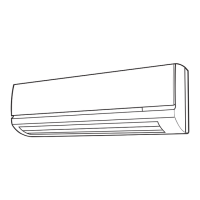
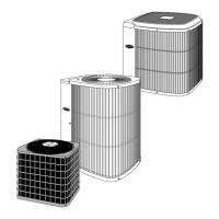
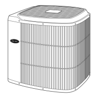
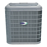
Describes three basic cabinet designs for AC and heat pumps.

INTERNAL CABINET ACCESS

Removing Top Cover and Fan Motor Assembly

Procedures for accessing internal components by removing covers and fan motor.

CONTROL BOX IDENTIFICATION

Base and Comfort Series AC Control Box

Identifies components within the AC control box.

Base and Comfort HP Control Box

Identifies components within the Heat Pump control box.

LABELING

Mid-Tier / Deluxe Label Locations

Shows locations of various labels on Mid-Tier/Deluxe units.

Entry Label Locations

Shows locations of various labels on Entry units.

ELECTRICAL

Aluminum Wire Usage

Guidelines for using aluminum wire in branch circuits and connections.

Contactor Operation and Testing

Explains the function and troubleshooting of contactors.

Capacitor Testing and Safety

Details capacitor testing procedures and safety precautions.

CYCLE PROTECTOR

CRANKCASE HEATER

TIME-DELAY RELAY

PRESSURE SWITCHES

Low-Pressure Switch (AC Only)

Protects against low suction pressures in AC systems.

High-Pressure Switch (AC & HP)

Protects against excessive condenser coil pressure in AC & HP.

Loss of Charge Switch (HP Only)

Detects loss of charge in heat pump systems.

DEFROST THERMOSTAT

DEFROST CONTROL BOARD

HK32EA001 DEFROST CONTROL

Describes the HK32EA001 control board for defrost timing and operation.

Troubleshooting HK32EA001

HK32EA003 DEFROST CONTROL

Quiet Shift (HK32EA003)

Field-selectable defrost mode to eliminate noise during defrost.

Five-Minute Compressor Delay (HK32EA003)

Protects compressor from short cycling with a 5-minute delay.

System function and Sequence of operation (HK32EA003)

Explains cooling and heating operation sequences for the HK32EA003 control.

Defrost Sequence

Describes the time/temperature defrost cycle initiation and termination.

Deluxe Defrost Speedup

Procedure to initiate a forced defrost cycle.

HK32EA008 DEFROST CONTROL

Quiet Shift-2 (non-communicating)

Defrost mode to reduce noise during defrost initiation and restart.

FAN MOTOR

COMPRESSOR PLUG

LOW-VOLTAGE TERMINALS

COPELAND SCROLL COMPRESSOR

LG SCROLL COMPRESSOR

DISCHARGE TEMPERATURE PROTECTION

COMPRESSOR TROUBLESHOOTING

Compressor Failures

Classifies compressor failures into mechanical and electrical types.

Mechanical Failures

Discusses mechanical issues where the motor appears normal but compressor doesn't function.

Locked Rotor Failure

Describes failure mode where motor draws locked rotor current and cycles off.

Runs, Does Not Pump Failure

Describes failure where motor runs but compressor doesn't pump refrigerant.

Noisy Compressor Causes

Lists various internal and external factors that can cause abnormal compressor noise.

COMPRESSOR NOISE TROUBLESHOOTING

IDENTIFYING COMPRESSOR TERMINALS

ELECTRICAL FAILURES

Single-Phase Motor Terminal Identification

Explains how to identify terminals C, S, and R for single-phase motors.

Open Circuit Testing

Tests for breaks in internal motor winding wires.

Ground Circuit Testing

Tests for shorts to ground in motor windings.

Short Circuit Testing

Tests for shorts between motor winding wires.

REFRIGERATION SYSTEM

Refrigerant Safety and Handling

Discusses Puron refrigerant safety, handling, and system requirements.

Roof Protection from Compressor Oil

Precautions for protecting synthetic roofing from compressor oil.

Brazing Techniques

Basic points and techniques for brazing refrigeration system components.

Service Valves and Pumpdown

Explains the function of service valves and the pumpdown procedure.

PUMPDOWN PROCEDURE

HEATING PISTON ACCURATER

REVERSING VALVE

LIQUID LINE FILTER DRIER

Installing Liquid-Line Filter Drier (AC Units)

Procedures for installing a liquid-line filter drier in AC indoor coils.

Installing Liquid-Line Filter Drier (HP Units)

Procedures for installing a liquid-line filter drier in HP indoor coils.

Suction Line Filter Drier

Discusses suction line filter driers for Puron systems and their usage.

ACCUMULATOR

THERMOSTATIC EXPANSION VALVE (TXV)

TXV Operation and Installation

Details TXV operation, mounting, and installation procedures.

TXV REPLACEMENT

Replacing TXV on Indoor Coil (Pre-2006)

Steps for replacing TXV on indoor coils for units manufactured before 2006.

Replacing TXV on Indoor Coil (Post-2006)

Steps for replacing TXV on indoor coils for units manufactured after 2006.

MAKE PIPING CONNECTIONS

REFRIGERATION SYSTEM REPAIR

Leak Detection Methods

Methods for detecting refrigerant leaks using electronic detectors and soap bubbles.

Coil Removal Procedure

Steps for removing evaporator and condenser coils for servicing.

COMPRESSOR REMOVAL AND REPLACEMENT

SYSTEM CLEAN-UP AFTER BURNOUT

SYSTEM EVACUATION

Deep Vacuum Method

Method for removing non-condensables and moisture using a vacuum pump.

Triple Evacuation Method

Method for evacuating systems with limited vacuum pump capabilities.

CHECK CHARGE

TROUBLESHOOTING WITH SUPERHEAT

Basic Diagnostics for Superheat Issues

Initial checks for proper airflow and subcooling before superheat diagnosis.

Low Superheat Troubleshooting

Diagnosing and resolving low superheat conditions in TXV systems.

High Superheat Troubleshooting

Diagnosing and resolving high superheat conditions in TXV systems.

Hunting Superheat Troubleshooting

Diagnosing and resolving hunting superheat, typically an application issue.

PSEUDO EVAPORATOR SUPERHEAT CALCULATION

TWO-STAGE 25HNB/24ANB APPLICATION GUIDELINES

Airflow Selection (Non-Communicating Thermostats)

Selects proper airflow for 2-stage units with non-communicating thermostats.

Airflow Selection for FV4C Fan Coils

Selects proper airflow for FV4C fan coils used with 2-stage units.

General Information for Two-Stage Units

Provides general information, including low ambient operation.

Low Ambient Cooling with Infinity Control

Details low ambient cooling capabilities for Infinity controlled systems.

MODEL PLUG

General Information for Two-Stage Units (Continued)

Defrost Operation and Settings

Explains defrost control options and operation cycles.

General Information for Two-Stage Units (Continued)

Quiet Shift and Quiet Shift-2 Modes

Explains defrost modes to reduce noise during transitions.

Forced Defrost Procedure

Initiates a defrost cycle manually.

Check Charge Procedure

Guidelines for checking and adjusting refrigerant charge.

SYSTEM FUNCTIONS AND SEQUENCE OF OPERATION

Cooling and Heating Operation Modes

Describes system operation in cooling and heating cycles.

Compressor Operation and Modulation

Explains the operation of the modulated scroll compressor.

Utility Interface With Infinity Control

How a utility device interrupts compressor operation via Infinity control.

Fan Motor Operation

Details the operation of the fan motor and its ECM variable speed control.

ECM FAN MOTOR TROUBLESHOOTING

TIME DELAYS

PRESSURE SWITCHES

MUFFLER, ACCUMULATOR, REVERSING VALVE

THERMISTORS

Outdoor Ambient Thermistor

Senses outdoor air temperature to activate system functions.

Outdoor Coil Thermistor (OCT)

Senses coil temperature for defrost and operation monitoring.

CONTROL BOX COMPONENTS

Contactor and Capacitor Identification

Identifies control box components like contactors and capacitors.

Incoming Power Connection

Details how incoming power is attached and grounding requirements.

TROUBLESHOOTING CONTROL BOARD

Systems Communication Failure

Addresses issues when communication with the User Interface is lost.

Model Plug Importance

Explains the function and installation of the model plug.

PRESSURE SWITCH PROTECTION

CONTROL FAULT AND BROWN-OUT PROTECTION

Control Board Failure

Actions taken when the control board fails or is detected faulty.

Brown-Out Protection

System response to low line voltage conditions.

BROWN-OUT PROTECTION DEFEAT

230V LINE AND COMPRESSOR VOLTAGE DETECTION

230V Line (Power Disconnect) Detection

Detects loss of 230v power to the compressor contactor.

Compressor Voltage Sensing

Monitors compressor motor run capacitor voltage status.

Contactor Shorted Detection

Detects if the contactor is stuck closed when no demand exists.

COMPRESSOR THERMAL CUTOUT AND CONTACTOR ISSUES

Compressor Thermal Cutout

Detects thermal protector opening and system lockout.

Contactor Open/Closed Faults

Addresses issues with contactors being open or closed improperly.

COMPRESSOR STAGING AND UNLOADER TEST

Troubleshooting Two-Stage Switching

Verifies proper switching between low and high compressor stages.

Unloader Test Procedure

Procedure to test the compressor's internal unloader mechanism.

TEMPERATURE THERMISTORS

Thermistor Sensor Comparison and Function

Compares sensors and checks for out-of-range conditions.

Failed Thermistor Default Operation

Explains default system operation when thermistors fail.

STATUS CODES AND TROUBLESHOOTING

WIRING DIAGRAMS

TWO-STAGE NON-COMMUNICATING UNITS

Operating Ambient Conditions

Details operating ambient limits for cooling and heating.

Airflow Selection for ECM Furnaces

How to select proper airflow for ECM furnaces.

Airflow Selection for Variable Speed Furnaces

How to select proper airflow for variable speed furnaces.

Airflow Selection for FV4C Fan Coils

How to select proper airflow for FV4C fan coils.

SYSTEM FUNCTION AND SEQUENCE OF OPERATION

Cooling and Heating Operation Modes

Describes system operation in cooling and heating cycles.

Compressor Operation Details

Explains compressor capacity modulation and operation.

Quiet Shift and Quiet Shift-2 Defrost Modes

Explains defrost modes to reduce noise during transitions.

Defrost Control and Speedup

Details defrost control functionality and forced defrost procedures.

HEATING CHECK CHART PROCEDURE

COMPRESSOR STAGING AND UNLOADER TEST

Verifying Two-Stage Switching

Checks proper switching between low and high stages for 25HCB6 units.

Unloader Test Procedure

Procedure to test the compressor's internal unloader mechanism.

CARE AND MAINTENANCE

Cleaning the Outdoor Coil

Steps for cleaning the outdoor coil to maintain performance.

Cleaning the Outdoor Fan Motor and Blade

Procedures for cleaning the fan motor and blade.

ELECTRICAL CONTROLS AND WIRING

REFRIGERANT CIRCUIT CHECKS

PURON REFRIGERANT QUICK REFERENCE GUIDE

Related product manuals