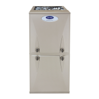
58MXB
Deluxe 4–Way Multipoise
Fixed-Capacity Condensing Gas Furnace
Installation, Start-Up, and Operating Instructions
Sizes 040-140, Series 100
NOTE: Read the entire instruction manual before starting the
installation.
NOTE: This furnace can be installed as a
(2-pipe) direct vent
or (1-pipe) non-direct vent condensing gas furnace.
This symbol → indicates a change since the last issue.
TABLE OF CONTENTS
SAFETY CONSIDERATIONS.....................................................2
CODES AND STANDARDS........................................................4
ELECTROSTATIC DISCHARGE (ESD) PRECAUTIONS........6
INTRODUCTION..........................................................................6
APPLICATIONS............................................................................6
General ......................................................................................6
Upflow Applications.................................................................6
Downflow Applications............................................................8
Horizontal Left (Supply-Air Discharge)
Applications ............................................................................10
Horizontal Right (Supply-Air Discharge)
Applications ............................................................................11
LOCATION..................................................................................14
General ....................................................................................14
Furnace Location Relative to Cooling Equipment ................15
Hazardous Locations...............................................................15
Furnace Location and Application.........................................15
AIR FOR COMBUSTION AND VENTILATION ....................16
INSTALLATION.........................................................................19
Leveling Legs (If Desired).....................................................19
Installation in Upflow and Downflow
Applications ............................................................................19
Installation in Horizontal Applications ..................................19
Air Ducts.................................................................................21
General Requirements .......................................................21
Ductwork Acoustical Treatment .......................................21
Supply Air Connections ....................................................21
Return Air Connections.....................................................21
Filter Arrangement..................................................................22
Bottom Closure Panel.............................................................23
Gas Piping...............................................................................23
Electrical Connections............................................................24
115–v Wiring.....................................................................25
24–v Wiring.......................................................................26
Accessories ........................................................................26
Removal of Existing Furnaces from Common
Vent Systems ..........................................................................27
Combustion Air and Vent Pipe Systems ...............................27
Condensate Drain....................................................................41
General...............................................................................41
Application.........................................................................42
Condensation Drain Protection .........................................42
START-UP, ADJUSTMENTS AND SAFETY CHECK...........42
General ....................................................................................42
Prime Condensate Trap With Water......................................43
Purge Gas Lines......................................................................43
Sequence of Operation............................................................43
Heating Mode....................................................................44
Cooling Mode....................................................................44
Thermidistat Mode ............................................................44
Continuous Blower Mode .................................................47
Heat Pump Mode...............................................................47
Component Test.................................................................51
Adjustments .............................................................................51
Set Gas Input Rate ............................................................51
Set Temperature Rise ........................................................55
Adjust Blower Off Delay (Heat Mode)............................55
Set Thermostat Heat Anticipator ......................................55
Check Safety Controls............................................................56
Check Primary Limit Control ...........................................56
Check Pressure Switch......................................................56
Checklist..................................................................................56
A93040
Visit www.carrier.com
Manufacturer reserves the right to discontinue, or change at any time, specifications or designs without notice and without incurring obligations.
Book 1 4
Tab 6a 8a
PC 101 Printed in U.S.A. Catalog No. 58MXB-1SI Pg 1 8-05 Replaces: 58MXA-18SI


 Loading...