EasyManua.ls Logo

Carrier WEATHERMAKER 8000 58WAV - User Manual

Carrier WEATHERMAKER 8000 58WAV
24 pages
Print Icon
To Next Page IconTo Next Page
Loading...
WeatherMaker 8000™
58WAV
Upflow Induced-Combustion Furnaces
Installation, Start-Up, and Operating Instructions
Sizes 045-155, Series 140 (LIMITED)
NOTE: Read the entire instruction manual before starting the
installation.
Index Page
SAFETY CONSIDERATIONS.....................................................1
ELECTROSTATIC DISCHARGE (ESD) PRECAUTIONS
PROCEDURE........................................................................2-3
Dimensional Drawing...............................................................2
Clearances From Combustible Materials.................................3
INTRODUCTION.....................................................................3
LOCATION ..............................................................................4
General.................................................................................4
Location Relative to Cooling Equipment...........................4
Hazardous Locations ...........................................................4
AIR FOR COMBUSTION AND VENTILATION..............4-6
Unconfined Space................................................................4
Confined Space....................................................................5
AIR DUCTS..............................................................................6
General Requirements .........................................................6
Ductwork Acoustical Treatment .........................................6
Supply-Air Connections ......................................................6
Return-Air Connections.......................................................6
FILTER ARRANGEMENT .....................................................6
LEVELING LEGS (IF REQUIRED).......................................7
GAS PIPING .........................................................................7-8
ELECTRICAL CONNECTIONS.............................................8
115-v Wiring........................................................................8
24-v Wiring..........................................................................8
Accessories.......................................................................8-9
VENTING.................................................................................9
START-UP, ADJUSTMENT, AND SAFETY CHECK..12-20
General...............................................................................12
Sequence Of Operation................................................12-15
Heating Mode ....................................................................13
Cooling Mode...............................................................13-15
Continuous Blower Mode .................................................15
Continuous Blower Speed Selection from Thermostat....15
Heat Pump Mode...............................................................15
Start-Up Procedures .....................................................15-16
Adjustments..................................................................16-20
Set Gas Input Rate.......................................................16-19
Set Temperature Rise...................................................19-20
Set Thermostat Heat Anticipator ......................................20
Check Safety Controls............................................................20
Checklist..................................................................................21
SAFETY CONSIDERATIONS
Installing and servicing heating equipment can be hazardous due to
gas and electrical components. Only trained and qualified person-
nel should install, repair, or service heating equipment.
Untrained personnel can perform basic maintenance functions
such as cleaning and replacing air filters. All other operations must
be performed by trained service personnel. When working on
heating equipment, observe precautions in the literature, on tags,
and on labels attached to or shipped with the unit and other safety
precautions that may apply.
Follow all safety codes. In the United States, follow all safety
codes including the National Fuel Gas Code (NFGC) NFPA
54-1999/ANSI Z223.1-1999 and the Installation Standards, Warm
Air Heating and Air Conditioning Systems (NFPA 90B)
ANSI/NFPA 90B.
In Canada, refer to CAN/CGA-B149.1- and .2-M95 National
Standard of Canada, Natural Gas and Propane Installation Codes
(NSCNGPIC).
These instructions cover minimum requirements and conform to
existing national standards and safety codes. In some instances,
these instructions exceed certain local codes and ordinances,
especially those that may not have kept up with changing residen-
tial construction practices. We require these instructions as a
minimum for a safe installation.
Wear safety glasses and work gloves. Have fire extinguisher
available during start-up and adjustment procedures and service
calls.
Recognize safety information. This is the safety-alert symbol
.
When you see this symbol on the furnace and in instructions or
manuals, be alert to the potential for personal injury.
Understand the signal words DANGER, WARNING, CAUTION,
and NOTE. These words are used with the safety-alert symbol.
DANGER identifies the most serious hazards which will result in
severe personal injury or death. WARNING signifies a hazard
which could result in personal injury or death. CAUTION is used
to identify unsafe practices which would result in minor personal
injury or product and property damage. NOTE is used to highlight
suggestions which will result in enhanced installation, reliability,
or operation.
ama
CERTIFIED
REGISTERED QUALITY SYSTEM
Visit www.carrier.com
Manufacturer reserves the right to discontinue, or change at any time, specifications or designs without notice and without incurring obligations.
Book 1 4
Tab 6a 8a
PC 101 Catalog No. 535-757 Printed in U.S.A. Form 58WAV-9SI Pg 1 1-00 Replaces: New

Other manuals for Carrier WEATHERMAKER 8000 58WAV

Question and Answer IconNeed help?

Do you have a question about the Carrier WEATHERMAKER 8000 58WAV and is the answer not in the manual?

Summary

Safety Considerations

Electrostatic Discharge (ESD) Precautions

Procedures to prevent electrostatic discharge damage to electronic components.

Introduction

Furnace Location Guidelines

Guidelines for selecting an appropriate installation location for the furnace.

Location Relative to Cooling Equipment

Recommendations for installing furnace near cooling equipment.

Hazardous Location Installation Precautions

Precautions for installing furnaces in hazardous locations like garages.

Air for Combustion and Ventilation

Combustion Air for Unconfined Spaces

Requirements for combustion and ventilation air in unconfined spaces.

Combustion Air for Confined Spaces

Requirements for combustion and ventilation air in confined spaces.

Air Ducts

General Air Duct Requirements

Design and sizing standards for duct systems and connections.

Ductwork Acoustical Treatment

Guidelines for internal acoustical lining and fibrous ductwork.

Supply-Air Connections

How to connect the supply-air duct to the furnace outlet.

Return-Air Connections

Proper connection of return-air ducts to the furnace casing.

Filter Arrangement

Filter Arrangement and Installation

How to determine and install the furnace filter.

Leveling Legs (If Required)

Leveling Legs Installation

Instructions for installing leveling legs if required for furnace placement.

Gas Piping

Gas Piping Installation

Requirements for gas piping installation according to codes and standards.

Electrical Connections

115-V Electrical Wiring

Instructions for making 115-V electrical connections to the furnace.

24-V Wiring Connections

How to make 24-V wiring connections for controls and accessories.

Electrical Accessories Connections

Connecting electrical accessories like humidifiers or air cleaners.

Venting

Venting System Installation

Proper sizing and installation of the furnace venting system.

Start-Up, Adjustment, and Safety Check

General Start-Up Procedures

Initial checks and requirements before operating the furnace.

Furnace Sequence of Operation

Detailed explanation of the furnace's operating modes and sequences.

Heating Mode Operation

Step-by-step description of the furnace operation in heating mode.

Cooling Mode Operation

How the furnace operates with cooling systems.

Continuous Blower Mode

Operation of the blower in continuous mode.

Continuous Blower Speed Selection

How to select different blower speeds via the thermostat.

Heat Pump Mode Operation

Furnace operation when connected to a heat pump system.

Furnace Start-Up Procedures

Step-by-step guide for starting up the furnace after installation.

Furnace Adjustments

Procedures for adjusting gas input rate and temperature rise.

Setting Gas Input Rate

How to determine and set the correct gas input rate for the furnace.

Setting Temperature Rise

How to measure and adjust the air temperature rise.

Setting Thermostat Heat Anticipator

Adjusting the thermostat's heat anticipator for proper cycling.

Checking Safety Controls

Verifying the proper operation of all safety control systems.

Installation and Start-Up Checklist

A comprehensive checklist for installation and start-up tasks.

Overview

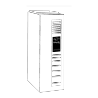
The document describes the WeatherMaker 8000™ 58WAV Upflow Induced-Combustion Furnaces, specifically models 045-155, Series 140 (LIMITED). This is a comprehensive installation, start-up, and operating instruction manual for these gas-fired furnaces.

Function Description:

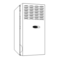
The WeatherMaker 8000™ 58WAV furnace is an upflow, induced-combustion, gas-fired heating appliance designed for indoor installation in residential and light commercial settings. It is certified for use with natural gas and can be converted to propane gas with an accessory kit. The furnace provides forced warm air for heating and is designed to integrate with air conditioning systems. Its primary function is to deliver efficient and reliable heating by burning natural or propane gas and circulating the heated air through a duct system. The induced-combustion design ensures efficient combustion and safe venting of flue gases.

Important Technical Specifications:

  • Model Series: 58WAV, Series 140 (LIMITED)
  • Input Capacities: 44,000 to 154,000 Btuh
  • Fuel Type: Natural gas (factory-shipped), convertible to propane gas with an accessory kit.
  • Installation Type: Upflow, indoor installation on combustible flooring, in alcoves, attics, basements, closets, or utility rooms. Not certified for mobile homes, recreation vehicles, or outdoors.
  • Altitude Certification: 0 - 10,000 ft (0-3,050m) for natural gas. Derating is required for altitudes above 2000 ft in the U.S.A. and 2000-4500 ft in Canada.
  • Electrical Requirements: 115-v, 60-Hz, 1-phase. Specific unit amps range from 5.9 to 14.4, with corresponding wire gages (12 or 14 AWG) and maximum fuse/circuit breaker amps (15 or 20 amps).
  • Return-Air Temperature: Minimum continuous 60°F db, intermittent operation down to 55°F db (e.g., with night setback thermostat). Maximum 85°F db.
  • Vent Type: Approved for Type B-1 Vent, and can be vented in common with other gas-fired appliances.
  • Manifold Pressure (Natural Gas): Approved range of 3.2-in. wc to 3.8-in. wc for altitudes up to 2000 ft. Adjustable from 2.0-in. wc to 3.8-in. wc for altitudes above 2000 ft.
  • Filter Information: Factory-supplied washable filters. Sizes vary by casing width (14-3/16", 17-1/2", 21", 24-1/2") and can be configured for side or bottom return.
  • Control System: Electronic control board with a 3-amp automotive-type fuse for the 24-v circuit. Includes terminals for thermostat connections (R, W, G, Y, C), humidifier (HUM), and electronic air cleaner (EAC-1, EAC-2).
  • Safety Controls: Manual reset limit switch or fuse link in the gas control area, flame rollout switches, pressure switch, and blocked vent safeguard switch.

Usage Features:

  • Thermostat Compatibility: Designed to work with single-stage and two-stage thermostats, including Thermidistat™ for enhanced dehumidification control.
  • Blower Operation: Multiple blower speeds (High, Medium-High, Medium-Low, Low) for different modes (COOL, FAN, HEAT, SPARE). Continuous blower mode is available. Blower off-delay is adjustable (90, 135, 180, or 225 seconds, factory set to 135 seconds).
  • Cooling Integration: Seamlessly integrates with 1-speed or 2-speed air conditioners and heat pumps (dual fuel applications). The control system manages blower speeds and timing for optimal cooling and dehumidification.
  • Humidifier and Electronic Air Cleaner Support: Dedicated 24-v terminals for humidifier connection (energized after inducer motor prepurge) and 115-v terminals for electronic air cleaner (energized during blower motor operation).
  • Diagnostic LED: The control board includes an LED for status codes, aiding in troubleshooting.
  • Component Test Feature: Allows individual components (except gas valve) to be run for a short period, assisting in system diagnosis.

Maintenance Features:

  • Filter Arrangement: Washable filters are supplied and can be easily accessed and relocated for side or bottom return configurations. Instructions are provided for cutting filters to fit specific casing widths.
  • Accessibility: Designed with ample space for servicing and cleaning. The blower compartment door must be in place for 115-v circuit completion.
  • Safety Control Checks: Procedures for checking the primary limit control, blocked vent safeguard switch, and pressure switch are detailed, ensuring safe operation and aiding in fault diagnosis.
  • Gas Input Rate Adjustment: Instructions for determining correct orifice size and manifold pressure, and for adjusting the gas valve regulator to achieve the specified input rate. This involves using a gas meter to clock gas flow.
  • Temperature Rise Adjustment: Guidance on measuring and adjusting the air temperature rise across the furnace by changing blower speed selections.
  • Thermostat Heat Anticipator Setting: Instructions for setting the thermostat heat anticipator based on the amp draw of the electrical components in the R-W circuit.
  • Troubleshooting: The manual provides a sequence of operation and diagnostic information (e.g., LED status codes) to assist trained personnel in identifying and resolving issues.
  • Service Training: Information on available packaged and classroom service training programs to enhance knowledge of the equipment, maintenance, and troubleshooting.

Carrier WEATHERMAKER 8000 58WAV Specifications

General IconGeneral
BrandCarrier
ModelWEATHERMAKER 8000 58WAV
CategoryFurnace
LanguageEnglish

Related product manuals