LHR Technologies, Inc. CarveWright™ System (Rev 1.39) 03/02/09 44
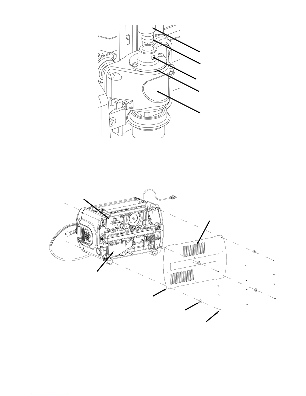
3. Remove the bottom cover. Carefully lay the machine on its back
with the dust collection port facing down. Remove the 12 screws
securing the black sheet metal cover onto the base (four of which are
located in the rubber feet) and remove it.
4. Check to see if the tie rod between the two leadscrews has
sufficient play. While the machine is still on its back, locate the
leadscrew tie rod. This tie rod (with bevel gears) connects the two
leadscrews on either side of the machine. The leadscrews drive the
FIGURE 34: VIEW OF THE FLEXSHAFT CONNECTION TO THE Z-TRUCK
F
IGURE 35: REMOVAL OF THE BOTTOM COVER
Bottom Closeout Cove
Cover Screw (12X)
Rubber Foot (4X)
Louvers (Facing into Machine)
Controller Box
Power Supply
Flexshaft Support Tube
Flexshaft Receptacle
End Of Flexshaft
Support Tube
Ball Deten
Z-Truck
 Loading...