LHR Technologies, Inc. CarveWright™ System (Rev 1.39) 03/02/09 45
head up and down as the crank handle is turned. Grab the tierod
and verify that there is side to side play in the rod. The amount of
play will vary between machines, but the important thing to note is
that there is some side to side play. The play should be minimal but
apparent. If the rod is locked side to side turn the crank handle one
full turn and try again. If the rod is still locked in place please contact
CarveWright technical support (713-473-6572) for additional
instructions.
5. Return the machine to its upright position. Be careful to not pinch
any of the base cables between the casting and the table. Crank the
head down to within 1” of the sandpaper belts.
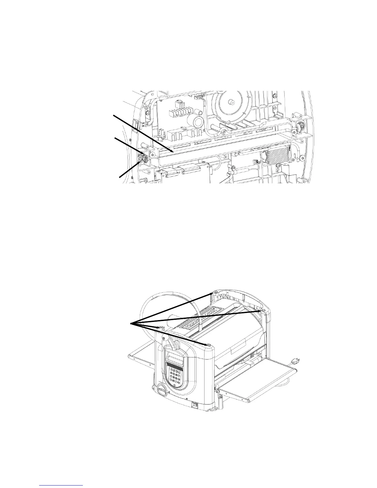
6. Loosen the screws securing the top of the four vertical guide
rods. Using a 10mm socket, loosen all four bolts attaching the
vertical guide rods to the top of the side panels. LOOSEN 1 to 2
TURNS ONLY - DO NOT REMOVE SCREWS.
FIGURE 36: LOCATION OF THE LEADSCREW TIE ROD
F
IGURE 37: LOCATION OF TOP VERTICAL GUIDE ROD SCREWS
Leadscrew Tie Rod
Tie Rod Bevel Gea
Leadscrew Bevel Gea
Top Guide Rod Screw
 Loading...