120V 60Hz Slow Blow
FUSE 8A 3AG 700VA
www.carvin.com
MADE
AUS
INTHE
SERIAL NUMBER
8 OHMS/CH
4 OHMS/CH
2 OHMS/CH
8Ω BRIDGED
4Ω BRIDGED
175W
250W
375W
500W
750W
INPUTS
1
2
MONO
BRIDGE
— + + —
OUTPUTS
1 2
PARALLEL
INPUTS
LIMITER
XLR
GND
LIFT
CH1
PIN 2 SIGNAL +
PIN 3 SIGNAL –
PIN 1 GND
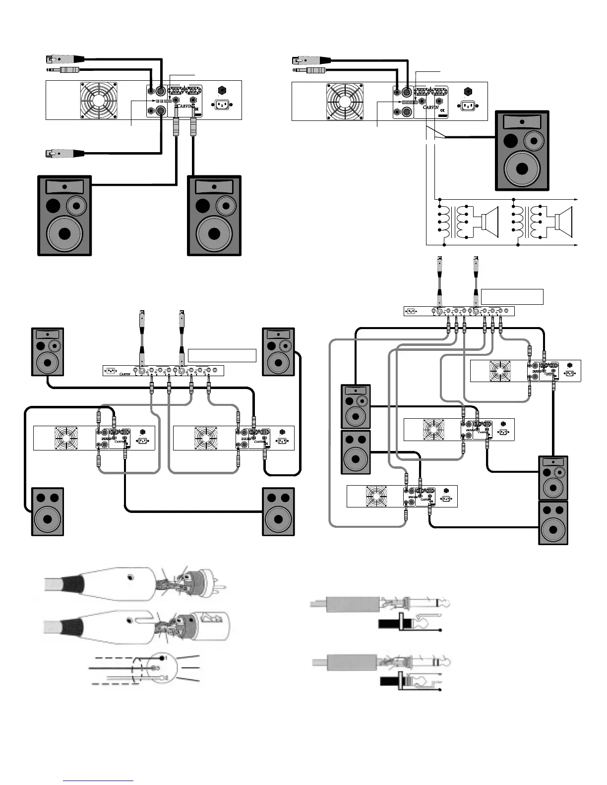
The channel PARALLEL switch OFF (OUT).
25V or 70V
Distribution System:
Wattage of transformer (TAP)
divided by total wattage
of Amp = Number of
transformer/speaker(s)
that can be hooked up.
or
To signal socket XLR or 1/4" 2 or 3 cond. shielded
Activate the BRIDGE switch
(IN). Control the level by Ch 1
( Ch 2 does not function.
Ch 1 Input
+
16
8
4
C
or
Single speaker or
system connected
in BRIDGE mode.
Minimum imp. 4Ω
15w
7w
3w
1w
C
+
16
8
4
C
15w
7w
3w
1w
C
25V OR 70V DISTRIBUTION SYSTEM
SHIELD
+POS.
2
1
3
-NEG.
SHIELD
+POS.
2
1
3
-NEG.
GND
- SIGNAL (BAL.)
+ SIGNAL (BAL.)
BALANCED MIC/LINE
(Shielded)
SPEAKER OR SIGNAL LINE CABLE
(Shielded or Unshielded)
SLEEVE
SLEEVE
TIP
TIP
* For monural (mono) systems, depress the PARALLEL button (IN) and only use CHANNEL 1 input (speaker hookup iden-
tical to stereo). Mono is normally recommended for live stage applications. Live stereo sounds great in the center of the
audience, however, the audience on one side will not hear the program material presented on the other side.
HELPFUL HINTS
speaker connector only and your bass response will improve.
6) THE AMP’S REAR CIRCUIT BREAKER TRIPS: When the red
CLIP LEDs are flashing at 2Ω (4Ω bridged), the rear circuit
breaker may trip. This is normal. Reset breaker & reduce level.
7) MAIN AC BREAKER TRIPS: Each high powered amp may require
a separate 20 amp circuit breaker (230V: 10 amp) for delivering
full power. Note: Some 120V homes have only 15 amp breakers.
1) NO SOUND FROM CH 2: The rear BRIDGE switch has been
inadvertently pushed in.
2) STEREO CHANNELS SOUND THE SAME: The rear
PARALLEL switch has been inadvertently pushed in.
3) NO HIGH FREQUENCIES: Tweeters or midrange drivers have
been damaged or blown from feedback or overpowering.
4) SYSTEM HUM: Try switching the GND LIFT switch IN or OUT
(depending on your use). If hum is not eliminated, then use a 600Ω
line input transformer cutting the input ground on the connectors
(Pin 1). This isolates the input ground from the AC power ground
eliminating a system ground loop.
5) POOR SOUND (BASS): The speaker systems are wired out
of phase to each other. To correct, reverse the wires on one
SHIELD (GROUND)
+ TIP (POS. SIGNAL)
STEREO TRIAMPING*
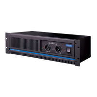
DCM1000
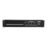
DCM1000
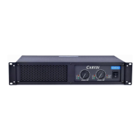
DCM1000
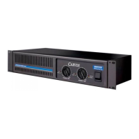
DCM1000
DCM1000
DCM1000
 Loading...