Do you have a question about the CARVIN XDrive DCM2000Lx and is the answer not in the manual?
Essential safety warnings regarding high sound pressure, electric shock, water, power sources, and cord protection.
Details Carvin's 3-year warranty, service procedures, and customer responsibilities.
Guidance on cleaning the unit and recording serial number, invoice number, and date.
Overview of DCM-Lx amplifiers, including stereo, bi-amp, bridging, DSP features, presets, and connectivity.
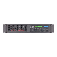
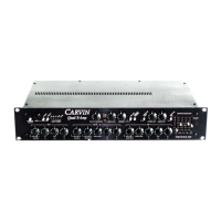
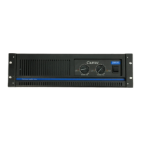
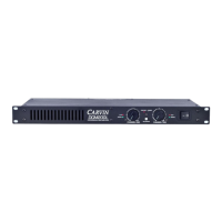
Details the front panel display, LEDs, level controls, and input/output connectors like XLR and Twist-Lock.
Explains the robust construction, high headroom power supply, and efficient switch-mode power topology.
Details the high-efficiency heat transfer system using aluminum heat sinks and multi-speed fans for cooling.
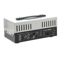
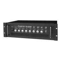
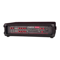
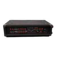
Describes the rear panel layout including USB, AC jack, XLR inputs, 1/4" TRS inputs, and speaker outputs.
Instructions for connecting AC power, safety warnings about defeating ground, and fuse information.
Details XLR inputs, 1/4" TRS inputs, ground lift switch, and Twist-Lock/binding post outputs for speaker connection.
Explains USB port usage for Xdrive control software and firmware updates.
Explains the SYSTEM and UTILITY buttons for accessing menus and the EXIT/MUTE button function.
Describes using Left/Right and Up/Down buttons for menu navigation and parameter adjustment.
Details channel select buttons (A/1, B/2, C/3, D/4) and indicator LEDs (SIG, CLIP, PROTECT, BRIDGE).
Describes how to adjust channel input levels using the volume attenuator controls.
Instructions on how to open, navigate, and exit the SYSTEM menu using the front panel buttons.
Guides users through the QUICK SETUP mode for configuring system routing and crossovers efficiently.
Lists available SYSTEM TYPE configurations like Mono2Way, Str2Way, Mono3Way, Mono4Way, and bridged options.
How to set input or output parameters and crossovers to a flat, wide-open state.
Process for copying channel settings from one input/output to another.
Explains how to combine amps for higher power output, including impedance notes.
Describes loading pre-optimized settings for specific CARVIN loudspeakers.
How to edit the system name by selecting and changing characters.
Procedure for saving the complete system configuration to a memory location.
How to recall a previously saved system configuration from memory.
Resets all input and output parameters and crossovers to a flat setting.
Instructions for opening, navigating, and exiting the UTILITY menu.
Configuring delay units, viewing available delay memory, and managing delay time.
Adjusting input sensitivity and configuring the turn-on mute function.
Managing security lockout, password, unit ID, and firmware version settings.
Instructions on how to mute individual or all outputs using the EXIT/MUTE button.
Explains how to cycle through display modes (Main, Input, Output) and use navigation buttons.
Adjusting the 30-band graphic EQ for incoming signals on each input.
Setting the output level (volume) for each channel to balance speaker levels.
Routing input signals (A, B, C, D) to specific outputs.
Adjusting the phase (0 or 180 degrees) of output signals for driver alignment.
Setting crossover frequencies and filter types (Butterworth, Bessel, Linkwitz-Riley) for LPF and HPF.
Setting the threshold for the limiter to prevent distortion and clipping.
Adding delay time to outputs for time-alignment or distance compensation.
Adjusting the four bands of parametric EQ for each output, including gain, frequency, and bandwidth.
Assigning a custom name to each output channel for easier identification.
Lists the minimum operating system requirements for Windows and Mac for the Xdrive software.
Step-by-step instructions for downloading and installing the Carvin Xdrive software.
How to connect the amp via USB, run the software, and recognize connected devices in the Xdrive interface.
Navigating the Xdrive control window, selecting devices, and understanding the remote control status.
Overview of system settings including load/save, name, sync, and firmware updates.
How to save, load systems, and edit the system name.
Details on syncing settings between the computer software and the DCM-Lx hardware.
Guide for updating the DCM-Lx amplifier firmware using the Xdrive software.
How to load or save preset input settings and select inputs.
Adjusting the graphic EQ settings for each selected input.
Copying input settings and resetting graphic EQ bands to flat.
Combining amp channels for bridging and muting individual outputs.
Selecting signal sources for outputs and assigning output names.
Manipulating Parametric EQs directly from the frequency chart interface.
Selecting outputs and copying settings between them.
Adjusting output gain, phase, limiter threshold, and delay time.
Configuring 4-band Parametric EQs and setting high/low pass crossover filters.
Step-by-step guide for configuring a 2-way bi-amp setup using LPF and HPF settings.
Instructions for setting up parallel outputs, routing input A to multiple outputs.
A detailed chart listing loudspeaker names and their corresponding processing settings.
Details on input impedance, output connectors, frequency response, and THD.
Specifications for DSP, EQ, crossover filters, limiter, delay, and parametric EQs.
Physical dimensions, weight, power requirements, and internal fuse ratings for different models.
Visual representation of the menu structure for System and Utility functions.
Illustrates the signal flow from inputs through DSP processing to amplifier outputs.
| Amplifier Type | Power Amplifier |
|---|---|
| Number of Channels | 2 |
| Impedance | 2, 4, 8 Ohms |
| Frequency Response | 20Hz - 20kHz |
| Signal to Noise Ratio | >100dB |
| Cooling | Variable speed fan |
| Input Impedance | 20 kOhms Balanced, 10 kOhms Unbalanced |
| Rack Units | 2U |
| Power Output (4 ohms) | 700W per channel |
| Connectors | XLR, 1/4" TRS |