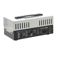
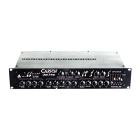
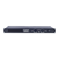
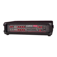
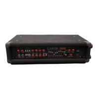
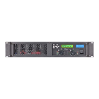
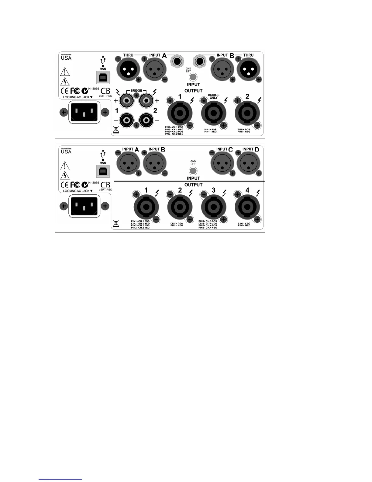
3. REAR PANEL
2ch. amp
4ch. Amp
AC POWER
Your amp will work at 50 or 60Hz with specific 100VAC, 120VAC, or 240VAC models.
Be sure to check your amp model and power source before plugging into a grounded
(3 prong) outlet. The standard IEC inlet accepts universal grounded AC cords.
Firmly push the AC cord all the way into the receptacle or the amp may be intermittent.
The receptacle will work with V-lock™ locking cords to prevent accidental unplugging.
*WARNING: Never defeat the grounded connection or electrocution may result!
*NOTE: Each amp requires a dedicated circuit breaker to achieve its full output.
Fuse: The fuse is located inside the main chassis near the AC inlet on the main PCB.
If the fuse fails the amp will usually require service. See specifications for fuse values.
INPUT: A, B, (C, D): XLR input connectors for audio signals
Check DSP settings if not working as expected.
Two channel amps include 1/4”(
TRS) inputs and XLR THRU outputs in parallel.
GND LIFT switch: Lifts the input connector grounds to solve ground loop issues.
OUTPUT: 1, 2, (3, 4): Speaker connections
Check the BRIDGE LED and DSP output settings for BRIDGE and ROUTING before
connecting to avoid malfunction or speaker damage.
Twist-Lock jacks accept 2-Pin or 4-pin Speakon™ compatible connectors.
Output 1 (or 3) allows Bi-Amping speakers through a single 4 conductor cable.
Binding Posts (on 2-ch.amps) allow bare wire connections up to 7ga. or “banana” plugs.
In BRIDGE mode use one of the following: the BRIDGE ONLY twist-lock output, the two
RED binding posts, or pins 1+ and 2+ on twist-lock OUTPUT 1 (or 3).
*Warning: Making additional connections to bridged amp outputs may misload the amp.
USB: Connect to PC/MAC to use Xdrive™ control software or to update DSP firmware.
6
 Loading...