Do you have a question about the CARVIN Tube 100 and is the answer not in the manual?
Ensure AC line voltage switch matches local voltage before connecting the power cord.
Connect line level sources to XLR or 1/4" inputs, select stereo or mono input.
Use 1/4" outputs for cabinets; set impedance switches and STEREO/BRIDGE switch.
Use BRIDGE jacks for cabinets; set impedance switches to half, and STEREO/BRIDGE to bridge.
Power preamp first, then amp. Set levels down, turn POWER on, then STANDBY on.
Check for shipping damage and notify carrier/CARVIN immediately if found.
Retain original carton and packing for future reshipment protection.
Keep invoice for warranty servicing and to verify received items.
Allow time for separately shipped items; contact CARVIN if items are missing.
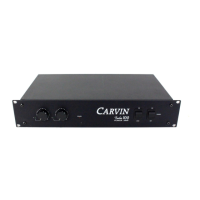
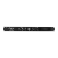
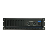
Describes the TUBE 100 as a 100W stereo tube power amplifier with multiple features.
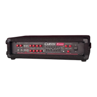
Push vertically to 'ON' to apply power; the indicator LED will light up.
Enables operation by removing plate voltage while keeping filaments on for tube life.
LED illuminates when power is applied to the unit.
41-step attenuators for adjusting output level, set to -10dB for normal operation.
Green LEDs monitor input signal strength post-level controls, indicating -30 dB presence.
Detachable three-conductor cord; never defeat the grounding pin.
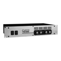
Accommodates 110/220V; use 3A slow-blow fuse, replaceable with a small screwdriver.
Set this switch to match your local line voltage before applying power.
Adjust presence (brightness) by rotating clockwise; counter-clockwise defeats it.
Accepts balanced XLR or unbalanced 1/4" inputs for low impedance sources.
Configures amp to receive mono (both channels from one input) or stereo input.
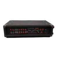
Set for 4, 8, or 16 ohm cabinets; impedances double in bridged mode.
Two 1/4" jacks for connecting cabinets in stereo mode.
Two 1/4" jacks wired in parallel for bridged mono operation (min 8 ohm load).
Switches amp to Mono Bridge mode for 100W mono output.
Connect preamp outputs to TUBE 100 inputs using XLR for lowest noise.
Connect TUBE 100 outputs to speaker inputs using heavy gauge wire (16 gauge or heavier).
Drives both channels from one input, requires setting MONO/STEREO switch.
Illustrates wiring for 8, 16, and 4 ohm total impedance using series/parallel connections.
Connect cabinets to BRIDGE jacks, set STEREO/BRIDGE to BRIDGE, IMP to half desired impedance.
Troubleshoot no indicator light by checking plug, circuit breaker, or fuse.
Check standby switch, input signal presence, and speaker cable connections.
Check impedance settings, line voltage, and EL34 power tubes.
May indicate a bad 12AX7 pre-amp tube.
Ensure fan vents are clear; allow amp to cool down.
Verify voltage setting or check for internal short; contact CARVIN.
Lists reference numbers, descriptions, part numbers, and quantities for all components.
100 watts total power.
20 to 20KHz.
Stereo (50w + 50w) or Mono bridged (100 watts).
Presence control per channel.
.5VAC for full power.
Greater than 20KΩ.
Balanced XLR, unbalanced 1/4".
Selectable 4Ω, 8Ω, 16Ω.
Four 1/4" jacks (2 mono bridge, 1 each stereo).
Four EL34 tubes.
Two 12AX7 tubes.
120/240 VAC 50-60Hz.
19"W x 10"D x 3.5"H, 28lbs.
One year parts and labor.
No charge for service, but shipping costs are customer's responsibility.
Contact for current flat rate charges including parts and labor.
Use own qualified technician; CARVIN ships parts pre-paid for warranty repairs.
Guaranteed against failure for one year; excludes misuse, inadequate care, natural disasters.