CARVIN ENGINEERING DATA OPERATING MANUAL
Pristine sound, brute power and no-fault reliability make the DCM amps the power
amp of choice for pro audio. Designed for continuous operation. Massive Toroid
power supplies with huge capacitors deliver the bass that kick drums demand --
you will feel the deep, resonating beat.
Mechanically the DCM's are more rugged than the import amps that are so preva-
lent today. Each DCM is hand built at our San Diego factory featuring all steel
construction, recessed controls and heavy-duty power components. The rock-
solid, efficient design with its superb, testimonial-proven sound, makes the USA
built DCM an amp you'll own for years.
PURE—TRANSPARENT SOUND
Carvin considers the sound of an amp equally important as its reliability. To
insure pure, uncolored sound, we designed one of the fastest power stages on
the market today. High slew rates of 50v/µs deliver superb transient response.
High frequencies are transparent and open—even at extreme levels. Linear feed-
back circuits reduce distortion to near the theoretical zero limit, preventing any
type of harshness which would lead to ear fatigue. The DCM Series amps deliver
flat, transparent, unaltered sound—especially important to the studio user. And
you can drive any type of reactive loads, including 70V transformer distribution
systems. These amps are designed to deliver non-stop, continuous RMS power
and are completely protected from heat and short circuits.
ULTRA RUGGED FOR TOURING
Every chassis is made from heavy-duty 16 gauge steel that is plated before
painted to prevent rust. All internal cabling is neatly tied and harnessed. Every
circuit card is FR-4 MILITARY SPEC, double-sided, through-hole plated, fire
retardant glass epoxy. This insures that the solder flows on the top, bottom
and through each hole of every component, preventing components from shak-
ing loose. Speakon™ connectors, heavy-duty power switches, recessed
knobs, all give the DCM amps a “tank-like” ruggedness.
TOROID POWER SUPPLY
Toroids deliver massive amounts of “on demand” current for continuous oper-
ation. This gives the power supply a solid foundation, yielding more headroom
for the large subwoofer applications. Not only do toroids deliver high current,
but they are known for reducing stray magnetic fields eliminating hum & noise.
This is especially important for the recording industry.
MODULAR CONSTRUCTION
With the DCM Series, Carvin brings you totally modular construction. If you
ever need an I/O (input/output) connector card because a connector wore-out,
just unplug it and re-install the replacement card in minutes. You don’t have
to de-solder anything. This applies to every aspect of the DCM Series amps
including the power supply, power cards, heat sinks and fans. Everything is
connected by heavy-duty AMP™ and MOLEX™ type connectors for easy replace-
ment—even the Toroid transformer is a total plug-in.
DISTORTION-FREE LIMITERS
The purpose of a limiter is to hold down peaks so the amp won’t distort even
with extra hot input signals (this protects your expensive speakers). In addi-
tion, a well designed limiter can increase your amp’s average output as much
as 3 db. Part of Carvin’s design uses the more expensive, distortion-free linear
“opto isolators”. Unlike amps that use FET controlled limiters which can inject
small amounts of distortion, the DCM Series limiters keep your sound pure
and uncolored!
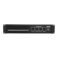
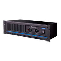
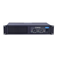
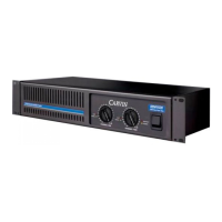
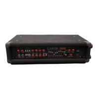
FRONT PANELS & CONNECTING UP
The DCM Series feature front panel signal, peak and protect LEDs which let you
monitor the status of the amp. All channels use precision level controls allow-
POWER AMP SPECIFICATIONS:
MODEL DCM1204
Both Channels RMS Continuous
4Ω (20-20k Hz, <1.0%) 300/300/300/300w
8Ω (20-20k Hz, <1.0%) 200/200/200/200w
Bridged RMS Continuous (ch 2-3)
8Ω, (20-20k Hz, <1.0%) 600w
THD (Typical—1/2 power): 0.03%
Damping Factor: >350
Slew Rate: bridged mode >50v/µs
Sensitivity: (4Ω, Vms) 1.0 V
Signal to Noise Ratio: Above 100dB
Frequency Response: ±0.5 dB, 20 Hz to 20kHz
(±1.5 dB, 10 Hz & 40 kHz)
Input Impedance: >20K Ω, balanced
Power Requirements:
120VAC 15 Amp circuit minimum
240VAC 8 Amp circuit minimum
Fuse Internal-above AC cord : 25AMP slow blow
Protection Circuits: Short Circuit • No Load Protection • SpeakerGuard™ • Thermal Shut-Off • Mute On/Off
Control and Indicators:
Front: Power switch • Recessed attenuators • Signal LED • Clip LED • Protect LED • Power Indicator
Rear: Ground Lift (each channel) • Parallel Input Switches • Speaker Output Bridge Switch • Limiters
IN/OUT Switch • Input Connectors: Four; Balanced 1/4” • Speaker Output Connectors: Three high-
current Twist-Lok (one bridged) & four 1/4” connectors
Dimensions: 3 1/2" High x 19" Wide x 10" Depth (2-space)
Net Weight: 23 lbs.
76-01204A 012704
DCM1204
RECEIVING INSPECTION—read before getting started
INSPECT YOUR UNIT FOR ANY DAMAGE which may have occurred during shipping. If any
damage is found, please notify the shipping company and CARVIN immediately.
SAVE THE CARTON & ALL PACKING MATERIALS. In the event you have to re-ship your unit,
always use the original carton and packing material. This will provide the best possible protec-
tion during shipment. CARVIN and the shipping company are not liable for any damage caused
by improper packing.
SAVE YOUR INVOICE. It will be required for warranty service if needed in the future.
SHIPMENT SHORTAGE. If you find items missing, they may have been shipped separately.
Please allow several days for the rest of your order to arrive before inquiring.
RECORD THE SERIAL NUMBER on the enclosed warranty card for your records. Keep your
portion of the card and return the portion with your name and comments to us.
USA customers register online at: www.carvin.com/registration
All other countries register online at: www.carvinworld.com/registration
DCM1204 POWER AMP
ing you to see your settings at a glance. Balanced 1/4” phone jacks are used to elim-
inate hum & noise. Speaker outputs feature 1/4” jacks and high-current Twist-Lok
connectors.
The rear professional accessory group offers a GROUND switch to remove the
chassis ground from the 1/4” input. Two Parallel input switches connect the inputs
of channels together eliminating Y connectors allowing amp patching in multiple
amp systems. The accessory group also features a bridge mode switch for deliv-
ering full power into a 70V distribution system and a limiter ON/OFF switch that
gives you the choice of using the internal limiter circuitry.