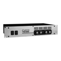
TYPICAL BRIDGE STEREO SETUP
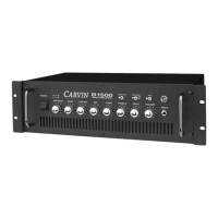
TYPICAL STEREO BIAMP SETUP WITH 2 DCM4000
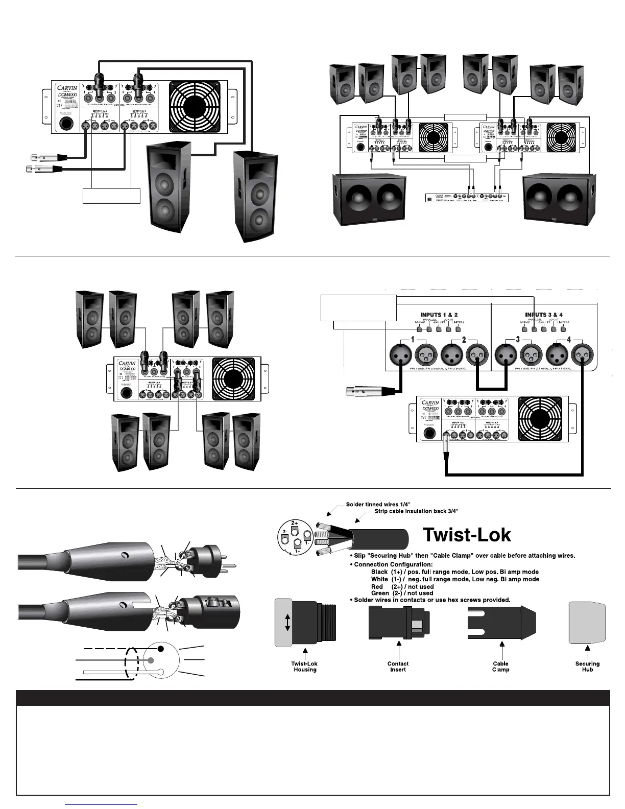
SHIELD
-NEG.
3
1
2
+POS.
SHIELD
-NEG.
3
1
2
+POS.
GND
- SIGNAL (BAL.)
+ SIGNAL (BAL.)
BALANCED MIC/LINE XLR CABLES
(Shielded)
HELPFUL HINTS
1. No sound from Ch 2 or 4:
The rear BRIDGE switch has been inadvertently pushed in.
2. Stereo channels sound the same:
The rear PARALLEL switch has been inadvertently pushed in.
3. No High Frequencies:
Tweeters or midrange drivers have been damaged or blown from
feedback or overpowering.
4. System hum:
Tr y switching the GND LIFT switch IN or OUT (depending on your use).
If the hum is not eliminated, then use a 600Ω line input transformer cutting the input
ground on the connectors (Pin 1). This isolates the input ground from the AC power ground.
5. Poor sound (poor bass):
The speaker systems are wired out of phase to each other. To correct, reverse the wires
on one speaker connector only and your bass response should improve.
6. Main AC breaker trips:
Each 120VAC DCM4000 amp will require two separate 20 amp circuit (240V: 25 amp)
to deliver its full sine wave power with a bench load.
4
4
4
4
4
XC3000 CROSSOVER
Ch 3
Ch 1
Left Highs
Right Highs
Left lows
Right Lows
BRIDGE switch
must be ON (in)
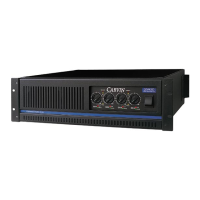
FULL LOAD SETUP
MULTI AMP INPUT SETUP WITH ONE INPUT SIGNAL
Ch 1
4
PARALLEL switch
must be ON (in)
BRIDGE switch must be ON (in)
2
2000W
2000W
2000W
“Bridged”
1st amp
2nd amp
XLR
cable
1
2
3
1000W
2
1000W
PARALLEL switch
must be ON (in)
2
1000W
2
1000W
4
4
 Loading...