1-23
(headphone or monitor send) or post-fader in which
case it would be used primarily for an effects send.
Rotating the Cue Send Master "Rotary" volume
controls will vary the intensity of signal appearing
at the Cue outputs. And. rotating the Effects Send Master
"rotary" valume controls will vary the intensity of
the signal appearing at the Effects Outputs.
99
99
))
))
EE
EE
ff
ff
ff
ff
ee
ee
cc
cc
tt
tt
ss
ss
SS
SS
ee
ee
nn
nn
dd
dd
JJ
JJ
aa
aa
cc
cc
kk
kk
ss
ss
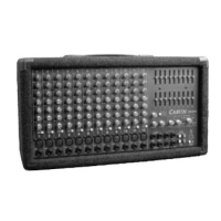
* These output jacks are identical to the Cue output jacks. They may be
selected for pre-fader operation to drive headphone systems or monitor systems,
and they may also be selected post-fader as an effects send. This "Effects Send"
output will connect to the input of your effect, and is of sufficiently low source
impedence to connect to any professional signal processing gear assuring the
best overall signal quality.
Remember" The Cue and Effects outputs may be used
interchangeably depending upon their pre/post fader selection at the fromt
panel of the console.
11
11
00
00
))
))
EE
EE
ff
ff
ff
ff
ee
ee
cc
cc
tt
tt
ss
ss
RR
RR
ee
ee
tt
tt
uu
uu
rr
rr
nn
nn
II
II
nn
nn
pp
pp
uu
uu
tt
tt
JJ
JJ
aa
aa
cc
cc
kk
kk
ss
ss
Quick Start Up
GETTING STARTED QUICKLY
If you're like most new owners, you're probably in a hurry to plug in your FET401 and use it. Here are some brief instructions to
get you going quickly. With the amp unplugged, turn the unit off and complete the following procedures:
1) CONNECTING AC POWER
• Check and change if necessary the rear AC Voltage Switch to the proper voltage. If a switch is not found, than pull out the Fuse
Holder (built into the AC cord receptacle) and turn it over to the proper voltage as seen on the holder—this automatically
switches the voltage and the fuse to the proper voltage and fuse value. On units with an AC Voltages Switch, change the fuse
as necessary (fuse values are listed on the rear panel).
• Use only a grounded (3 prong) power outlet to prevent a shock hazard. This gives the quietest grounding for your amp.
2) CONNECTING SPEAKERS
• Use the two 1/4" speaker jacks on the rear panel or the Red and Black speaker binding post. Be sure all your speakers are
properly wired in "Phase" with each other (positive and negative speaker terminals connected correctly to each other). The
Red binding post is the positive connection while the Black binding post is negative. Use only Heavy-Duty speaker cables (16
ga for 50', 14 ga for 100').
NOTE: Do not run your speakers through microphone wire or multi-conductor microphone junction boxes or "snakes" as sometimes
referred to. This wire is normally a very light 20 gauge wire causing a substantial loss of power through the cable for less power
to your speakers. All speaker wires must be
non-shielded to prevent the power amplifier from oscillating at high frequencies.
3) CONNECTING INPUTS
• For high line level balanced output devices plug into the balanced "MIC" XLR input at the rear of the FET401. Use a 3 conductor
shielded cable.
• For high level non-balanced inputs, plug into the "LINE" 1/4" input jacks on the rear panel. Use a 2 conductor shielded cable.
NOTE: This will also accept a balanced 1/4" signal if you wire the balanced signal to a stereo phone plug.
4) TURNING ON THE FET401
• Adjust the level control to the
off position.
 Loading...