QUICK START UP
If you’re like most new owners, you’re probably in a hurry to
plug your mixer in and use it. Here are some brief instruc-
tions to get you going quickly. With the mixer unplugged and
the unit turned off, complete the following procedures:
A. CONNECTING AC POWER TO YOUR MIXER
• Be sure to plug your mixer into the proper voltage for your
country, either 120V-60Hz or 240V-50Hz. The PA1200R
accepts both voltages listed.
• Use only a grounded (3 prong) power outlet to prevent a
shock hazard. This gives the quietest grounding for your
mixer.
B. CONNECTING INPUTS TO YOUR MIXER
• For balanced microphones, use a shielded cable and plug
into the XLR MIC inputs.
• For high output devices like instruments & keyboards, plug
into the LINE input jacks using a shielded cable. Depress
the GAIN switch “IN” for mic or “OUT” for instruments.
C. TURNING YOUR MIXER ON
• Set all channel and master LEVEL controls to their OFF
positions
• Set all HI, MID, and BASS controls and the graphic equal-
izers to their center “flat - no boost or cut” position.
• Adjust all channel “PAN” controls to their center position.
• Connect your speakers and monitors at the rear panel.
• Turn the mixer on by the rear POWER SWITCH and watch
for the front POWER LED to come on. Your mixer is now
ready to operate by turning the levels up.
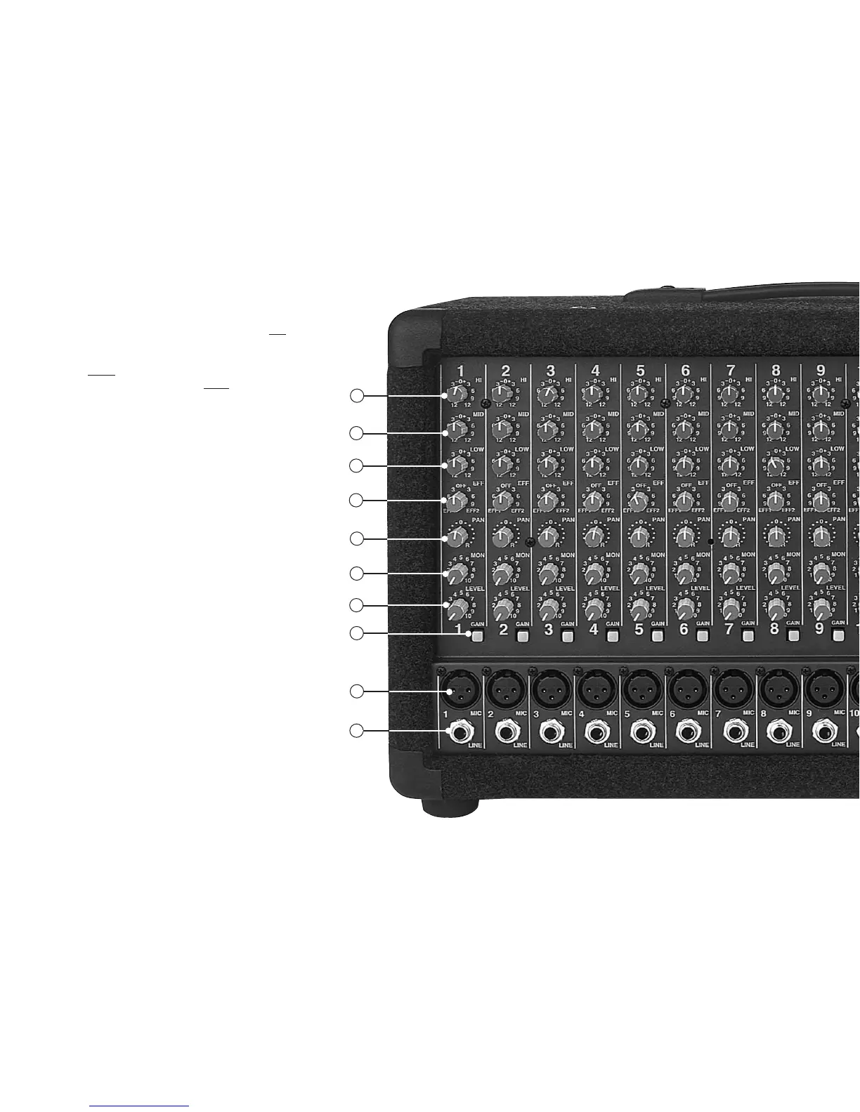
MIC CHANNEL FEATURES
1. LINE INPUT JACK
The LINE input is a 1/4” phone jack designed for balanced or
unbalanced line or instruments. Examples of these inputs
would be guitar, keyboard or CD player. The line input can be
used at the same time the mic input is being used.
2. XLR MICROPHONE INPUT
The XLR MIC input is designed for balanced low impedance
microphones. The high performance, low noise preamps do
a superb job of noise reduction. The XLR connector is wired
as per the industry standard, pin 1 is ground, pin 2 is non-
inverting (positive), and pin 3 is inverting (negative). Note:
Make sure the phantom power is switched off before con-
necting or disconnecting microphones to the mixer. It is rec-
ommended to allow 5 seconds for the phantom power to dis-
charge before making any microphone connections.
3. GAIN SWITCH
The GAIN switch increases the input sensitivity on both the
LINE and MIC input jacks by 20dB. Depress the GAIN switch
“IN” for mic or “OUT” for instruments. If distortion is heard,
the input source is overdriving the input stage. Disengage
the GAIN switch to the “OUT” position.
4. CHANNEL LEVEL CONTROL
The LEVEL control adjusts the volume of the channel before
going to the PAN control. Here is where the individual chan-
nel volumes are adjusted to make up the desired mix at the
main outputs. A general rule to prevent internal overdriving,
is to keep the MAIN master LEVEL the same or higher than
the channel LEVEL.
5. MONITOR LEVEL CONTROL
The MON level control adjusts the volume of the channel
going to the master monitor send. The monitor level control
is a pre-channel level control. This means it is unaffected by
adjustments from the channel level. The purpose for this is
the main mix adjustments can be made without disturbing
the monitor mix.
6. CHANNEL PAN CONTROL
The PAN control puts the channel into the LEFT, RIGHT or
CENTER in the stereo main outputs. If stereo placement is
needed, set the PAN control to the full RIGHT or LEFT position.
7. CHANNEL EFFECTS 1&2 LEVEL
The EFF 1&2 adjusts the level sent to the dual effects proces-
sors and to the EFF SND 2 jack. The effects control is post-
channel level, which automatically tracks the channel’s
LEVEL & tone controls. Turning this control to the left will
send to the internal effects processor 1. Turning to the right
will send to the internal effects processor 2 (and the external
EFF 2 SND jack). Reduce these levels if PEAK LEDs are flash-
ing on the effects processors.
8-10. CHANNEL TONE CONTROLS
Each channel features active 3-band tone controls LO, MID,
and HI. All three function as boost (clockwise) & cut
(counter-clockwise) controls. The center 0 is the “flat” or no
effect position. The LO and HI controls are shelving type
with corner frequencies at 80Hz and 11.5k Hz respectively.
The MID control is a band pass type centered at 750Hz.
Recommended setting: LO & HI +4, MID at -4. For electric
guitar, set the MID at -6 to -12 to add clarity.
MASTER SECTION FEATURES
11. MAIN MASTER LEVEL (AMPS 1&2)
The MAIN control is the master volume control for all chan-
nels. The MAIN signal is sent to the GRAPHIC EQ that feeds
the power amps and the RIGHT and LEFT XLR output jacks.
12. MONITOR MASTER LEVEL (AMP 3)
The MONITOR master level is sent to the GRAPHIC EQ (if
switched “IN”) and feeds the MONITOR power amp 3 and
XLR output jack.
13. EFF 2 SEND JACK
The EFF 2 SEND jack can send a signal to an external proces-
sor. This is the same signal sent to the internal EFF 2 processor.
14. RETURN LEVEL &
L-R RETURN JACK
The RETURN level control and L-R jack provides another
input into your mixer. It is most commonly used for an out-
board effects processor returning the signal from the EFF 2
SND, or as another input from a stereo source or instru-
ment.
A stereo TRS (Tip, Ring, Sleeve) cable will send the Tip signal
to the L and the Ring signal to the R. Inserting a mono plug
partially (first "click") will send a mono signal to both L-R.
15. L-R XLR OUTPUT CONNECTORS
The L-R professional balanced XLR line outputs are post
graphic EQ connectors. Use these to feed additional power
amps or recording gear. Note: If the INSERT jacks are being
used for patching, the new signal will be present.
16. MONITOR XLR OUTPUT CONNECTOR
This line output is the same signal that feeds the internal
MONITOR AMP 3. Use this professional balanced XLR out-
put for additional power amps.
17. PRE EQ INSERTS 1 AND 2
These jacks allow you to inject a signal into the master sec-
tion of the mixer. This insert is before the GRAPHIC EQ
using a stereo (tip ring sleeve). The TIP is the SEND and the
RING is the RETURN. The typical use of these jacks are for
the insertion of a compressor or other outboard gear
between the master preamp and the EQ. If a mono plug is
inserted into these jacks, the channels are disconnected
from the power amps.
18. TAPE JACKS
The L-R TAPE IN RCA inputs are ideal for connecting a CD or
tape player. These TAPE IN jacks can also be used for returning
another stereo effects processor or instrument (keyboard).
PA800, PA1200, PA1200R CONTROLS
1
4
5
6
3
2
7
8
9
10
 Loading...