18. TAPE JACKS CONT.
The L-R TAPE OUT RCA
jacks sends the MAIN signal (pre graphic EQ) for recording.
If the TAPE OUT is being used to record, make sure the
TAPE IN control is turned OFF to avoid feedback. The TAPE
OUT jacks are another way to access the output of the mas-
ter section if the INSERT jacks are being used.
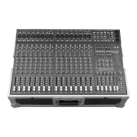
19. DSP PROCESSORS
Two 24-Bit proces-
sors provide a host of
great sounding
effects including
Flange, Reverb, Echo,
& Chorus. The chan-
nel EFF 1&2 send
controls delivers the
signals to the dual processors. Note: Reduce these levels if
the red PEAK LEDs are flashing on the processors.
Turn up the EFFECTS control to 5 on the processor(s) to add
your effects, while at the same time adjust the SELECT and the
PARAMETER controls to get the desired effect. Note: An audi-
ble noise will be heard while adjusting the effects.
EFFECT PARAMETERS
Each of the four effects has a variable parameter that can be easily
adjusted. Each “SELECT” & “PARAMETER” is described below.
A) ECHO: SELECT the amount of the regeneration (repeat-
ing). Now select the PARAMETER control for the shortest or
longest delay time between the original signal and the echo.
B) REVERB: SELECT the amount of presence (high frequen-
cies) in the reverb. Now turn the PARAMETER control to pro-
vide the minimum or maximum decay.
C) CHORUS: SELECT the amount of reverb with your chorus.
Now turn the PARAMETER control to increase the depth.
19. DSP PROCESSORS CONT.
D) FLANGE: SELECT
the amount of speed with your flange (phasing effect). Now
turn the PARAMETER control to increase the depth.
20. DSP PK 1, PK 2 LED’s
The DSP PEAK LED indicates that the signal level to the
processor is too high. To prevent distortion, turn the EFF 1-2
control towards the center (off) position until the PEAK LED
stops flashing.
21. EFF TO MONITOR CONTROL
The EFFECTS TO MONITOR level controls the amount of the
effects that goes into your monitors.
22. TAPE IN LEVEL
You may use the TAPE IN level as another input into your
mixer using the RCA TAPE IN jacks.
23. AMP “CLIP” LED’s
The amp CLIP LEDs indicate when the power amps are
starting to distort (clip). Reduce the MAIN 1-2 and/or
MONITOR 3 master volumes to prevent distortion.
24. POWER LED
The Power LED indicates when the mixer is powered up.
25. PROTECT LED
The mixer will “protect”, engaging relays to mute the speak-
ers if: a) impedance is below 4Ω on any amplifier b) short-
ed speaker cables, or c) ventalation problems. If this LED
comes on, shut the mixer “OFF” and check for cable prob-
lems, proper impedance and obstructed rear cooling vents.
If you encounter an over-heat problem, leave the mixer
“ON” allowing the fan to cool down the internal compo-
nents. The mixer will auto-reset. If a problem persists,
please contact Carvin’s service dept. 800-854-2235.
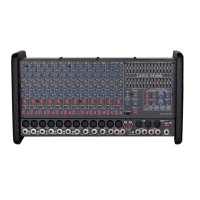
26. GRAPHIC EQUALIZER SWITCH
The EQ button will switch the EQ’s from LEFT-RIGHT to
MONO/MONITOR. The “OUT” position puts both EQ’s in the
L-R MAIN mix only. EQ1 is for the LEFT amp and EQ2 is for
the RIGHT amp. The “IN” position will combine the L-R mix
into EQ1 as a mono mix. Then the monitor mix is routed
through EQ2 for use with the MONITOR 3 amp to help control
stage feedback.
27. ADJUSTING THE GRAPHIC EQUALIZER
When the EQ sliders are in their center position, they do not
affect the audio signal. When EQ sliders are raised or low-
ered from this position, they boost or cut respectively a nar-
row frequency band. To reduce feedback in the low fre-
quency range, try lowering one of the 63, 125 or 250 Hz
sliders. High frequency feedback is reduced by lowering
one of the 2k or 4k Hz sliders.
To help with feedback reduction, the main speaker should
always be placed in front of the microphones.
For tone enhancement you may want to raise the 63, 125 (for
deeper bass)
and the 4, 8 and
16k (for crisper
highs) forming
a “smile” curve
as shown.
28. EFFECTS FOOT SWITCH JACK
The optional FS22 will remotely
shut off EFFECTS 1 or 2.
29. PHANTOM POWER
SWITCH AND LED
The PHANTOM power switch turns on the microphone
phantom power in the channel XLR jacks. This power is
used for supplying a voltage to condenser microphones.
The LED indicates the phantom power is turned on. The
phantom power will not damage conventional dynamic
microphones. Note: Make sure the phantom power is
switched off before connecting or disconnecting micro-
phones to the mixer. It is recommended to allow 5 seconds
for the phantom power to discharge before making any
microphone connections.
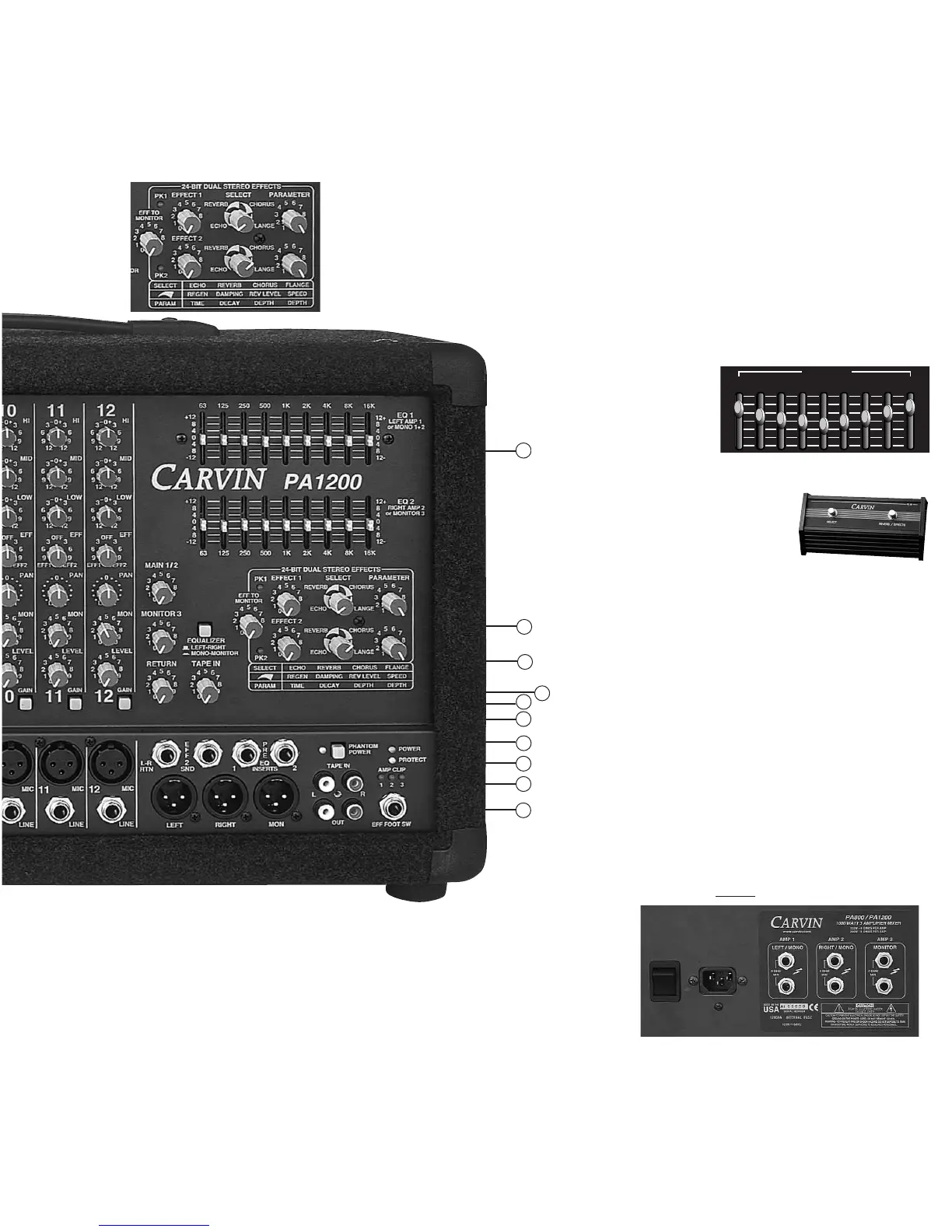
REAR PANEL-POWER/SPEAKER CONNECTIONS
The rear panel contains the POWER SWITCH and AC power
cable connection. For the PA800 and PA1200, there are 3
groups of 1/4” speaker jacks. Each group has two 1/4” out-
puts (wired in parallel). AMPS 1 and 2 are for the LEFT and
RIGHT speakers. AMP 3 is for the MONITOR speakers.
NOTE: 4Ω MIN IMPEDANCE PER AMPLIFIER (Maximum one
4Ω or two 8Ω speakers per amp). MAKE ALL SPEAKER
CONNECTIONS BEFORE TURNING THE MIXER ON .
 Loading...