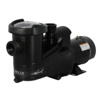
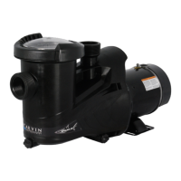
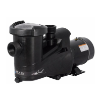
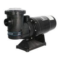
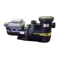
EasyManua.ls Logo

CARVIN SHARKJET User Manual

CARVIN SHARKJET
16 pages
Go to English
To Next Page IconTo Next Page
Page #1 background imageLoading...
Page #1 background image
POMPE POUR PISCINES CREUSÉES
INGROUND POOL PUMP
BOMBA PARA PISCINAS ENTERRADAS
MANUEL DU PROPRIÉTAIRE
OWNER’S MANUAL
MANUAL DEL USARIO
Utilisez seulement des pièces de remplacement d’origine.
Use Only Genuine Replacement Parts.
Utilice sólo piezas de repuesto originales.
M22904937A
WWW.CARVINPOOL.COM
ATTENTION - LIRE CE MANUEL ATTENTIVEMENT AVANT D’INSTALLER, D’OPÉRER LA POMPE SHARKJET. IL
CONTIENT DES INFORMATIONS IMPORTANTES RELIÉES À UNE UTILISATION SÉCURITAIRE DE CE PRODUIT
WARNING - READ THIS MANUAL BEFORE INSTALLING AND OPERATING SHARKJET PUMP. IT INCLUDES IMPORT-
ANT INFORMATION ABOUT SAFE USE OF THIS PRODUCT.
ADVERTENCIA: LEA ESTE MANUAL ANTES DE INSTALAR Y OPERAR LA BOMBA SHARKJET. INCLUYE INFOR-
MACIÓN IMPORTANTE SOBRE EL USO SEGURO DE ESTE PRODUCTO.
Question and Answer IconNeed help?

Do you have a question about the CARVIN SHARKJET and is the answer not in the manual?

CARVIN SHARKJET Specifications

General IconGeneral
Horsepower1.5 HP
Voltage115/230V
Max Flow Rate90 GPM
Wet End MaterialThermoplastic
Connection Size2"
Port size2" NPT

Summary

Important Safety Instructions

Suction Entrapment Hazard Prevention

Mitigate suction entrapment risks by ensuring proper connection to outlets, preventing serious injury or death.

Child Supervision and Product Use

Ensure children are closely supervised when using this product to prevent accidents and injury.

Electrical Safety: GFCI and Grounding

Connect to GFCI-protected receptacles and ensure proper grounding to prevent electrical shock hazards.

Power Cord Care and Replacement

Avoid burying power cords and replace damaged cords immediately with the specified type by a qualified electrician.

Extension Cord Prohibition

Do not use extension cords; always provide a properly located electrical outlet for safe operation.

Safe Pump Placement for Child Access

Position the pump at least five feet from the pool to deter children from using it as a means of access.

General Pump Information

Pump Features and Construction

Details self-priming capabilities, glass-reinforced thermoplastic construction, and internal components like impeller and diffuser.

Installation and Connections

Optimal Pump Installation Site

Locate pump near pool, min 5ft away, in dry, shaded, ventilated area on a level, vibration-free surface.

Piping System Design

Use simple, airtight piping, support pipes, and keep suction line below water to prevent air pockets.

Electrical Wiring Requirements

Ensure correct voltage connection (230V), use a fused disconnect, and employ a qualified electrician for wiring.

Operation and Maintenance Guide

Pump Priming and Startup

Prime pump at high speed, check for air leaks, and verify full water flow within minutes of starting.

Controlling Pump Water Output

Maintain open suction valve; use return line valve to regulate pump flow and pressure as needed.

Lubrication, Draining, and Servicing

No lubrication needed. Drain pump via plugs, open valves for complete draining, and switch off power for servicing.

Strainer Basket Cleaning

Follow steps to switch off power, remove, clean, and replace the strainer basket to maintain performance.

Dismantling and Troubleshooting

Strainer Nut Installation

Align markers, insert, and tighten strainer nut clockwise 1/4 turn to secure the cover.

Shaft Seal Replacement Procedure

Handle seal components with care, avoid lubricants on seal faces, and install moistened ceramic face correctly.

Frequently Asked Questions

Addresses common issues like motor start failure, low speed, overheating, no water delivery, low capacity, and noise.

Dimensional Specifications

Provides detailed measurements of the pump for installation planning and reference.

Pump Disassembly Steps

Base Removal

Remove the base by sliding it backward after detaching the retaining screw.

Motor Removal

Detach the motor from the body by removing four bolts and the cap motor.

Diffuser Removal

Unscrew the diffuser from the motor bracket using a 1/4" socket.

Impeller Removal

Secure the motor shaft and unscrew the impeller by hand.

Ceramic Seal Removal

Use a flat screwdriver to carefully remove the ceramic seal ring and its rubber housing.

Replacement Parts and Warranty

Replacement Parts Identification

Lists part numbers, descriptions, and figures for all pump components, aiding in reordering.

Warranty Information

Details limited warranty periods, specific exceptions for components like light bulbs, and general conditions.

Warranty Claim Procedure

Outlines the process for making a warranty claim, including initial contact, inspection, and purchaser responsibilities.

Related product manuals