QUICK ST
ART UP
If you’re like most new owners, you’re probably in a hurry
to plug your mixer in and use it. Here are some brief instruc-
tions to get you going quickly. With the mixer unplugged and
the unit turned off, complete the following procedures:
A. CONNECTING AC POWER TO YOUR MIXER
• Be sure to plug your mixer into the proper voltage marked
on your mixer, either 120V-60Hz or 240V-50Hz.
•
Use only a grounded (3 prong) power outlet to prevent a
shock hazard (do not bypass). This gives the quietest
grounding for your mixer.
B. CONNECTING INPUTS TO YOUR MIXER
• For balanced microphones, use a shielded cable and plug
into the XLR
MIC inputs.
• For high output devices like instruments & keyboards, plug
into the
LINE input jacks using a shielded cable. Adjust the
GAIN control for mic or for instruments.
C. TURNING YOUR MIXER ON
• Set all channel and master LEVEL controls to their OFF
positions
• Set all
HI, MID, and BASS controls and the graphic equal-
izers to their center
“flat - no boost or cut” position.
• Connect your speakers and monitors at the rear panel.
• Turn the mixer on by the rear
POWER SWITCH and watch
for the front POWER LED to come on. Your mixer is now
ready to operate by turning the levels up.
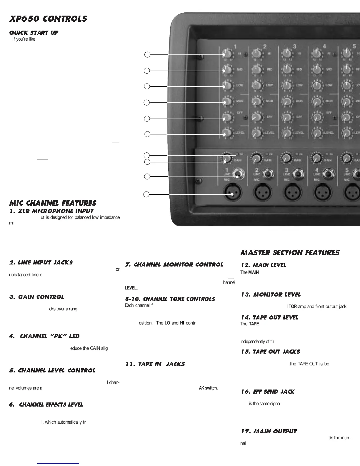
MIC CHANNEL FEATURES
1. XLR MICROPHONE INPUT
The XLR MIC input is designed for balanced low impedance
microphones. The high performance, low noise preamps do
a superb job of noise reduction. The XLR connector is wired
as per the industry standard, pin 1 is ground, pin 2 is non-
inverting (positive), and pin 3 is inverting (negative). Note:
Make sure the phantom power is switched off before con-
necting or disconnecting microphones to the mixer.
2. LINE INPUT JACKS
The LINE input is a 1/4” phone jack designed for balanced or
unbalanced line or instruments. Examples of these inputs
would be guitar, keyboard or effect returns. The line input
can be used at the same time the mic input is being used.
3. GAIN CONTROL
The GAIN control adjusts the input sensitivity on both the
LINE and MIC input jacks over a range of 40dB. For quietest
operation, set the
GAIN control just below the point where
the
PK LED
flashes. If the PK LED lights or if distortion is
heard reduce the
GAIN slightly until the PK LED is off
.
4.
CHANNEL “PK” LED
The PK LED indicates when the channel is nearing it’s clip-
ping level, causing distortion. Reduce the GAIN slightly to
prevent distortion. To get more volume, increase the master
MAIN control and re-adjust your main mix.
5. CHANNEL LEVEL CONTROL
The LEVEL control adjusts the volume of the channel before
going to the PAN control. Here is where the individual chan-
nel volumes are adjusted to make up the desired mix at the
main outputs.
6. CHANNEL EFFECTS LEVEL
The EFF control adjusts the level sent to the effects proces-
sor and to the front EFF SND jack. The effects control is
post-channel level, which automatically tracks the channel’s
LEVEL
& EQ controls. Reduce the
EFF level if the PK LEDs
are flashing on the effects processor.
7. CHANNEL MONITOR CONTROL
The MON control adjusts the volume of the channel going to
the master
MONITOR control.
The
MON control is a
pre
-
LEVEL control. This means it is unaffected by the channel
LEVEL.
8-10. CHANNEL TONE CONTROLS
Each channel features active 3-band EQ tone controls LO,
MID, and HI. All three function as boost (clockwise) & cut
(counter-clockwise) controls. The center 0 is the “flat” or no
effect position. The
LO and HI controls are shelving type
with corner frequencies at 80Hz and 11.5k Hz respectively
.
The
MID control is a band pass type centered at 750Hz.
These settings will vary with the type of voice or instrument.
Try reducing the MID to add clarity and turn up the LO and
HI for a fuller sound.
11. TAPE IN JACKS
The T
APE IN
inputs on CHANNEL 6 are for connecting a CD or
tape player. These TAPE IN jacks can be used for returning
another effects processor or instrument (keyboard).
Channel 6
inputs are NOT muted by the MUSIC BREAK switch.
MASTER SECTION FEATUR E S
12. MAIN LEVEL
The MAIN control is the master volume control for all chan-
nels. The
MAIN signal is sent through the MAIN GRAPHIC
EQ to the MAIN amp and the front MAIN output jack.
13. MONITOR LEVEL
The MONITOR master level is sent through the MONITOR
GRAPHIC EQ to the MONITOR amp and front output jack.
14. T
APE OUT LEVEL
The TAPE OUT LEVEL sends the MAIN signal mix to the
TAPE OUT jacks for recording. The TAPE OUT level is unaf-
fected by the MAIN level control so a recording level can be set
independently of the MAIN speaker volume.
15. T
APE OUT JACKS
Use the TAPE OUT L-R jacks for recording or to send to
external power amps. If the TAPE OUT is being used to
record, make sure the TAPE IN jacks are not connected to
the recorder output or turn the channel 6 LEVEL to “0” or
feedback will result.
16.
EFF SEND JACK
The EFF SEND jack can send a signal to an external processor.
This is the same signal sent to the internal effects processor.
Effect returns can be connected to any input channel
.
Make
sure the EFF control for the return channel is set to “OFF” or
“EFF1” or feedback will occur.
17. MAIN OUTPUT
The front MAIN output is the same signal that feeds the inter-
nal MAIN amp. Use this balanced 1/4” output to feed addi-
tional power amps, etc..
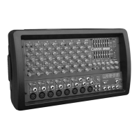
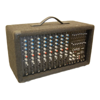
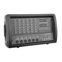
XP650 CONTROLS
1
4
5
6
3
2
7
8
9
10
 Loading...