Do you have a question about the CAS EXI-200AD and is the answer not in the manual?
Introduction to safety, defining 'Warning' and 'Alert' for safe product use.
Details critical warnings like avoiding disassembly, proper plug insertion, grounding, and cord handling.
Details cautionary notes on handling, installation location, and avoiding damage or errors.
Specifies the product's use in hazardous locations with gas, steam, or chemical exposure.
Covers guidelines for transporting the explosion-proof indicator, including packaging.
Details requirements for assembling and installing the explosion-proof indicator.
Details requirements for inspecting and adjusting the explosion-proof instrument.
Details the procedure for operating the product, including checks and cautions.
Lists critical cautions and prohibitions to follow during product operation.
Describes the requirements for continued management and periodic inspection of the instrument.
Provides a detailed table of the EXI-200AD's technical specifications.
Highlights the key features such as high speed, accuracy, and microprocessor adoption.
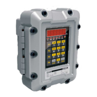
Presents the physical dimensions and external views of the indicator.
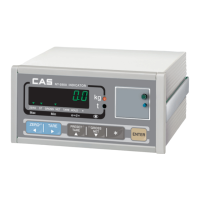
Explains the components on the front surface: display, keys, and wiring inlets.
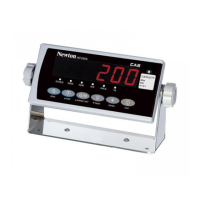
Shows the layout of the EXI-200 keypad for user interaction.
Provides an overview of the internal components and connectors of the indicator.
Explains the purpose of weight calibration for accurate measurement.
Explains how to set the maximum capacity for the weighing scale.
Explains how to use the zero-set function to establish a zero point for weighing.
Provides instructions on how to access the instrument's various test modes.
Details the procedure for testing the functionality of each key on the keypad.
Explains how to perform a display screen test to check all indicators.
Outlines the serial communication test procedure to verify data transmission.
Explains how to test external input and output signals, if the option is installed.
Provides instructions on accessing the instrument's configuration (Set Mode).
Details settings for device ID, baud rate, and port configuration for communication.
Explains configuration options for the analog output (A-Out) feature.
Covers settings for device date, time, and Alibi memory usage.
Outlines network configuration settings for TCP/IP communication.
Explains settings related to printer type, form, and print conditions.
Configures AD speed, average filter, low-pass filter, and band-stop filters.
Manages stable weight range, auto-zero, weight back-up, key functions, hold settings, and key lock.
Configures serial ports, baud rates, data formats, and communication methods for RS-232, RS-485, and RS-422.
Sets analog output range, V-out, I-out, dual output, and zero/span adjustments.
Configures the device's date, time, and Alibi memory functionality.
Sets whether memory overwriting is enabled or disabled.
Sets relay modes (Limit, Checker, Programmable) and output behavior based on weight.
Configures external inputs and the relay display status.
Configures DHCP, TCP mode, IP addresses, subnet masks, and gateways for network setup.
Configures printer type, print forms, data management, line feeds, and head messages.
Lists calibration mode errors and their corresponding solutions.
| Capacity | 200g |
|---|---|
| Display | LCD |
| Calibration | External Calibration |
| Operating Temperature | 5°C ~ 40°C |
| Weighing Units | g, oz, ozt, dwt, ct, gn |
| Power | AC adapter or 4 AAA batteries |
| Measurement Range | 0-200g |
| Power Supply | AC adapter or 4 AAA batteries |