Do you have a question about the CAS NT-200 Series and is the answer not in the manual?
Essential safety guidelines for operating the weighing indicator to prevent damage or injury.
Information regarding CAS dealer services for installation, maintenance, and inquiries.
Key capabilities and operational advantages of the NT-200 Series weighing indicator.
Essential operational modes and capabilities of the NT-200 Series weighing indicator.
Technical details regarding load cell interface and analog-to-digital conversion.
Technical specifications for the display, character size, and indicators.
Details on standard and optional communication ports and protocols.
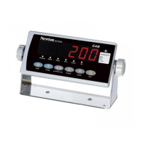
Diagram and measurements for the NT-200A and NT-201A series weighing indicators.
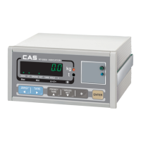
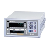
Diagram and measurements for the NT-200S and NT-201S series weighing indicators.
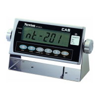
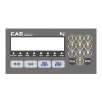
Overview of the NT-201A front panel, including buttons and display indicators.
Explanation of the status indicators on the weighing indicator's display.
Detailed descriptions of indicator lamps like STABLE, ZERO, TARE, and NET.
Explanation of the keypad functions and operations for the weighing indicator.
Details on the ENTER and UNIT key operations on the front panel.
Diagram and identification of ports on the rear of NT-200A/201A models.
Diagram and identification of ports on the rear of NT-200S/201S models.
Detailed explanation of the various ports found on the rear panel.
Instructions for correctly connecting the load cell to the indicator.
Steps to enter the diagnostic test mode of the weighing indicator.
Overview of the different diagnostic tests (TEST1 to TEST6) available.
Procedure for testing the RS-232 serial communication with a computer.
Procedure for testing RS-422/485 communication (optional).
Steps to verify the functionality of the connected printer.
Instructions for entering the System Mode for configuration.
Overview of available modes within System Mode (Weight, Count, Percent, Accumulation).
Detailed steps for configuring the Count Mode settings.
Detailed steps for configuring the Percent Mode settings.
Explanation of key functions like ZERO, TARE, GROSS/NET in specific modes.
Description of key functions within the Accumulation Mode.
Procedure for entering the Calibration Mode via the CAL switch.
Explanation of the different calibration types and key functions.
Steps for performing weight calibration, including unit selection.
Configuration for multi-point calibration settings.
Setting the maximum weight capacity for the scale.
Setting the minimum division or resolution for the scale.
Steps for performing zero point calibration on the scale.
Setting specific weights for calibration points.
Performing span calibration using specified weights.
Configuration options for gravity compensation based on location.
Configuration for stable condition detection and judgment.
Setting for automatic zero tracking based on percentage of max capacity.
Enabling or disabling kilogram to pound weight conversion.
Detailed steps for performing the zero calibration.
Accessing and exiting engineer and calibration modes.
Instructions for physically sealing the indicator after calibration.
Procedure for entering the Function/Set Mode.
List of configurable functions (F01-F10) in Set Mode.
Configuration for hold type and live-stock delay time.
Settings for display back-light and buzzer alerts on errors.
Settings for checker and limit modes, including output signals.
Choosing the method for accumulation in weighing operations.
Configuring the lock status for various keys on the panel.
Setting the range or type for password protection.
Steps to change the device's password.
Settings and parameters related to device identification and operation.
Setting a unique identification number for the device.
Configuring the use of the COM1 (RS-232) port for communication.
Selecting the transmission method for COM1.
Configuring baud rates for RS-232 and RS-422 communication.
Configuring the use of the COM2 (RS-422) port.
Selecting the transmission method for COM2.
Choosing the type of printer connected to the device.
Configuring automatic printing based on weight stability or limit conditions.
Setting the number of line feeds for print output.
Choosing between different print formats.
Configuring how the date is printed.
Configuring whether to print the Product ID.
Configuring how user messages are printed.
Configuring the device's internal clock and date.
Introduction to using the weighing indicator in its primary mode.
Procedure for assigning product identification numbers.
Configuring upper and lower weight limits for items.
Manually entering tare weight values.
Entering tare values associated with specific product IDs.
Retrieving tare values based on product IDs.
Steps for providing sample quantity for counting operations.
Directly entering values for count mode operations.
Steps for providing sample weight for percentage calculations.
Directly entering values for percent mode operations.
Wiring diagrams for connecting the indicator to a PC via COM1.
Details on RS-485/422 options and real-time clock functionality.
Wiring diagrams for connecting the indicator to a printer via COM2.
Explanation of the CAS ASCII code protocol for data exchange.
Details of the Limit Protocol for status and value reporting.
List and description of commands for controlling the indicator.
Description of variables used in the CAS DLP protocol.
Protocol for custom user messages.
Glossary of abbreviations displayed on the indicator screen.
List of error messages and their corresponding solutions for troubleshooting.
| Brand | CAS |
|---|---|
| Model | NT-200 Series |
| Category | Measuring Instruments |
| Language | English |