5-ASSEMBLY
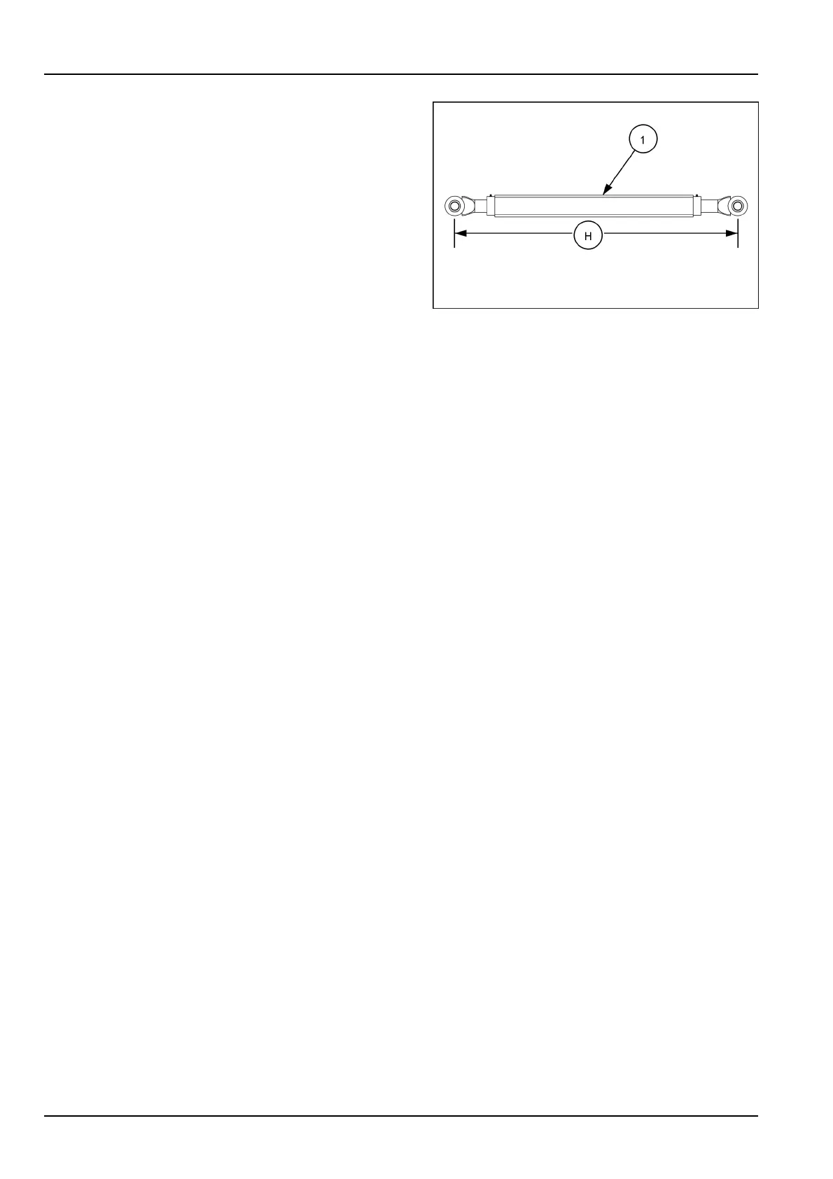
1.Adjusttheinitialdistance(H)betweenthecenterof
theturnbuckleclevisesonthemainframegaugewheel
turnbuckleassembly(1)to1206.5mm(47-1/2in).
2.Positionthemainframegaugewheelturnbuckleas-
sembly(1)tothelowermountoftherockerpivot(A).
NOTE:Orienttheturnbuckleassembly(1)withtheadjust-
mentdecaltowardsthefrontoftheimplement.
SAVM19TIL0749AA2
3.Assemblethewasher(C)(removedduringdisassem-
bly)overthe32x152mm(1-1/4x6in)pin(D)(re-
movedduringdisassembly).
4.Insertthe32x152mm(1-1/4x6in)pin(D)through
thelowermountoftherockerpivot(2)andthemain
framegaugewheelturnbuckleassembly(1).
5.Insertthe3/8x2inslottedspringpin(2)throughthe
holeinthe32x152mm(1-1/4x6in)pin(D).
6.Positiontheadjustmentwrench(3)ontothemainframe
gaugewheelturnbuckleassembly(1).
7.Positionthemainframegaugewheelturnbuckleas-
sembly(1)tothelowermountingholeinthelower
gaugewheellinkassembly(G).
8.Insertthe3/8x2inslottedspringpin(2)throughthe
holeinthe32x152mm(1-1/4x6in)pin(5).
9.Assembletwowashers(4)onthe1-1/4x6-1/2inpin
(5).
10.Insertthe1-1/4x6-1/2inpin(5)throughthelower
gaugewheellinkassembly(G)andthemainframe
gaugewheelturnbuckleassembly(1).
11.Insertthe3/8x2inslottedspringpin(2)throughthe
holeinthe1-1/4x6-1/2inpin(5).
5-2
EN



 To Next Page