SECTION 58 - ATTACHMENT/HEADERS - CHAPTER 2
58-2
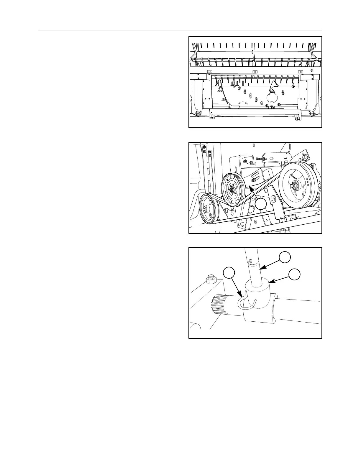
The feed auger transports grain cut along the length
of the head to the center where it is pushed by the
fingers into the combine feeder head. The auger is
driven by a chain connected to the left drive shaft. A
spring loaded slip clutch will prevent damage to the
drive train in the event that the auger becomes
jammed with product or foreign objects.
Fingers are installed along the length of the auger to
assist the movement of product towards the center of
the unit. The fingers become fully extended toward
the front of the auger, and almost completely
withdrawn as the unit rotates them to the back. This
is accomplished by using an off center, stationary
crankshaft inside the hollow auger.
10007570
1
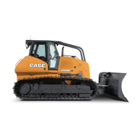
The crankshaft is held stationary on the right side of
the head by the adjusting arm, 1. Adjustments are
made to finger timing by positioning the arm.
The individual shafts are slid into clamping blocks
and tightened. Roller bearings and locking collars
are used at various points along the shaft to maintain
the units’ position in the auger, and to allow the auger
to rotate around the crankshaft.
50023020
1
2
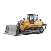
The auger fingers, 1, are attached to the stationary
crankshaft using mounting tee’s, 2, and hairpin
cotters, 3. The tee’s are manufactured from a plastic
material, and are therefore subject to breakage.
Several spare mounting tee’s are installed on various
portions of the crankshaft.
10008316
3
2
1
3