SECTION 58 - ATTACHMENT/HEADERS - CHAPTER 2
58-9
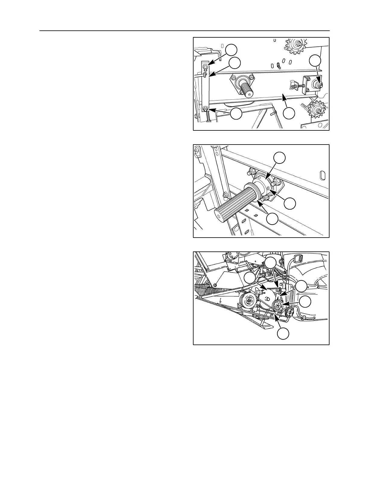
10. Slide the channel/bearing assembly, 1, on the
auger drive shaft. Set the strip, 2, into place.
Secure the strip and channel assembly using
three carriage bolts and nuts, 3.
50040102
3
2
3
3
1
22
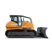
11. Place the eccentric locking collar, 1, on the shaft
bearing and rotate it opposite of the direction of
rotation. Strike the collar with a punch and
hammer to set the lock. Tighten the set screw, 2.
Slide any spacer washers, 3, that were removed
during disassembly into position on the shaft.
50040101
3
2
1
23
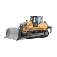
12. Slide the sprocket, 5, onto the shaft and secure
with the washer, lock washer, and cap screw.
13. Install the auger chain. Tighten the chain using
the tensioning sprocket, 4, so that there is 0 ± 3
mm sag at the center of the longest span.
14. Attach the idler pulley frame, 3, to the head.
Install the idler pulley, 1, and drive belt, 2. Adjust
the idler pulley to allow 16 mm (5/8″) deflection
with 111 N (25 lbs.) force at mid-span on the lower
strand.
15. Remove tow motors or other devices used to
support the weight on the auger.
20023026
1
2
3
4
5
24