SECTION 58 - ATTACHMENT/HEADERS - CHAPTER 2
58-28
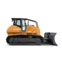
18. Tighten all clamping bolts, 1, and bearing
hardware that were loosened/removed to
perform this repair.
10007690
1
69
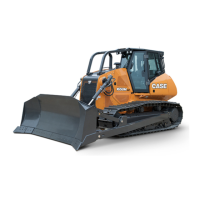
19. Slide the channel/bearing assembly, 1, on the
auger drive shaft. Set the strip, 2, into place.
Secure the strip and channel assembly using
three carriage bolts and nuts, 3.
50040102
3
2
3
3
1
70
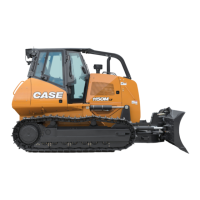
20. Place the eccentric locking collar, 1, on the shaft
bearing and rotate it opposite of the direction of
rotation. Strike the collar with a punch and
hammer to set the lock. Tighten the set screw, 2.
Slide any spacer washers, 3, that were removed
during disassembly into position on the shaft.
50040101
3
2
1
71
 Loading...