SECTION 58 - ATTACHMENT/HEADERS - CHAPTER 2
58-27
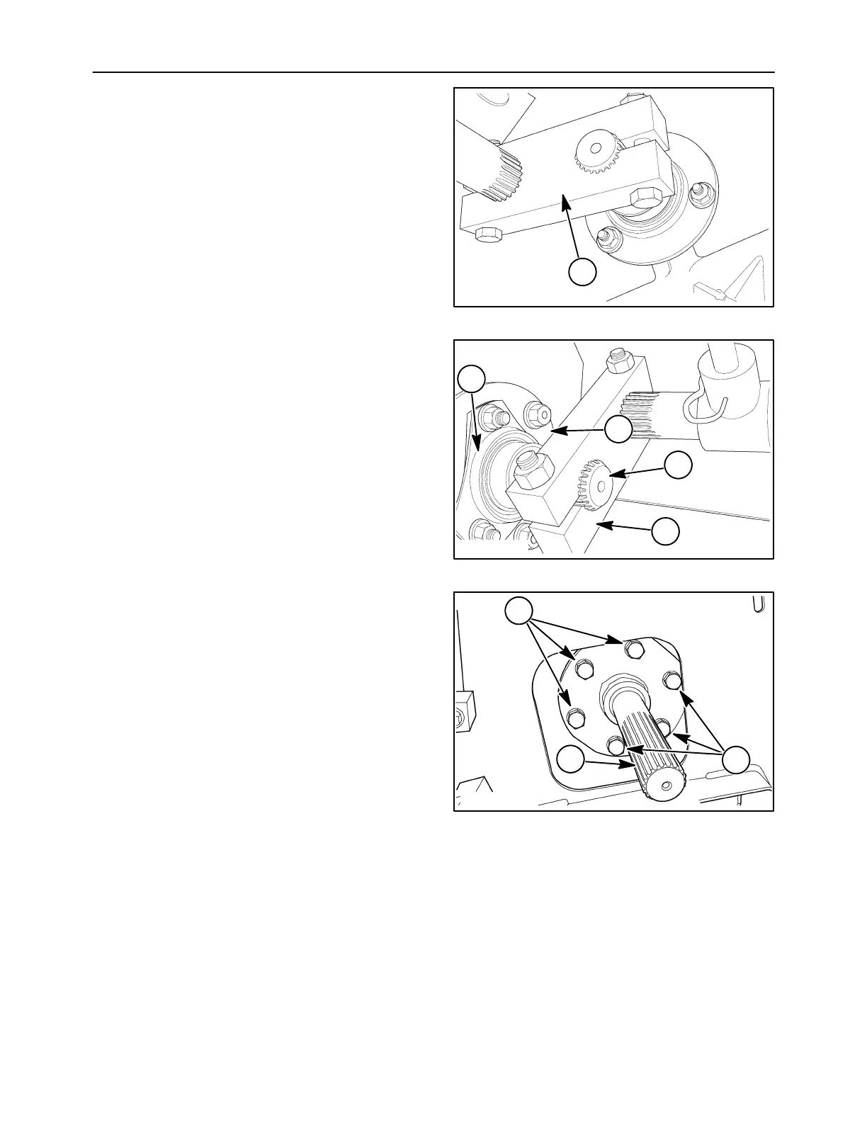
15. Engage the spline end of each shaft into the
clamp block, 1, before it until, all shafts are in
place. Ensure the same position is maintained
throughout the assembly. Loosely attach each
bearing to its mounting plate.
10008319
1
66
16. Insert the crank end shaft, 1, into the clamping
block, 2. Set the mounting plate, 3, into position,
and loosely attach the bearing, 4.
10008320
2
1
3
4
67
17. Set the auger drive shaft, 1, into position. Attach
the shaft using six cap screws, 2. The three short
cap screws will turn into the holes with the
threads close to the surface. The three longer
cap screws are used in the holes where the
threads cannot be seen from the surface.
2
50040103
2
1
68
 Loading...