SECTION 58 - ATTACHMENT/HEADERS - CHAPTER 2
58-26
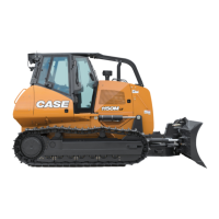
13. Remove the bearing mounting hardware, 1,
disengage the clamp blocks, 2, and lift out the
shaft(s) until the affected shaft can be accessed.
10008319
2
1
64
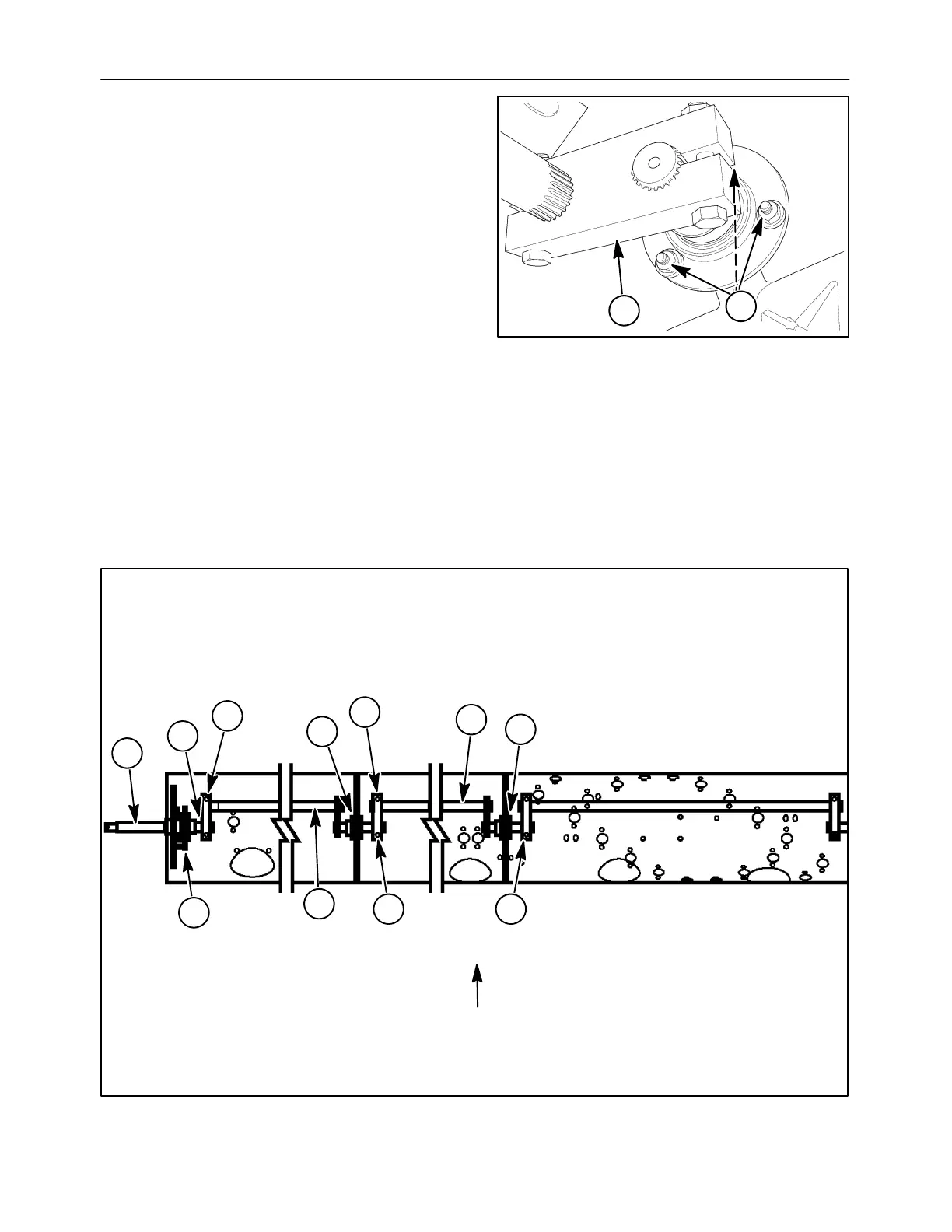
EXAMPLE: Shaft, 1, must be removed for repair.
Remove drive shaft, 2, mounting plate, 3, and left end
shaft, 4. Loosen clamping bolts, 5. Free bearings, 6,
from mounting plates. Take out shaft, 7, to the left.
NOTE: Spare finger mounting tees should be
installed during shaft replacement.
14. Set the new or repaired shaft into position along
the assembly.
IMPORTANT: Timing of the shafts is extremely
important. When assembled, the shafts should be in
a straight line. Install the repaired or new shaft in the
same position. If the shafts are not lined up, the
fingers may be fully extended at the rear of the auger.
If insufficient clearance exists in this position for the
fingers, damage will occur.
10008321
LEFT RIGHT
TOP
1
5
6
55
7
3
2
4
5
6
65
 Loading...