22-22
REFACING INTAKE AND EXHAUST VALVES
Before refacing the valves, they should be
wire brushed, cleaned and inspected. A 45°
angle is the correct valve face grinding
angle. Set the refacing machine protractor
at this angle. Be sure the chuck of the mach-
ine is clean before installing the valve.
Dress the grinding wheel before starting to
reface the valves. Take only light cuts as
the valve is refaced. The last cut must be
very fine so the valve face will have a pol-
ished finish.
IMPORTANT -
Replace anyvalvethathas
a thin edge or margin, Figure
25.
If
the
margin on the ground valve is less than half
the margin on anew valve, replace the valve.
VALVE FACE \
l
GRINDING A~N~G~L=E~_):~~~~,===,:=
T
MARGIN
1
~
CHAMFER
l
TIP
Figure 25
The tip end of the valve should be checked
for roughness .or wear. Usually this can be
removed with some very light cuts against
the side of the grinding wheel and will square
up the end. Never grind off the valve stem
end beyond the chamfer.
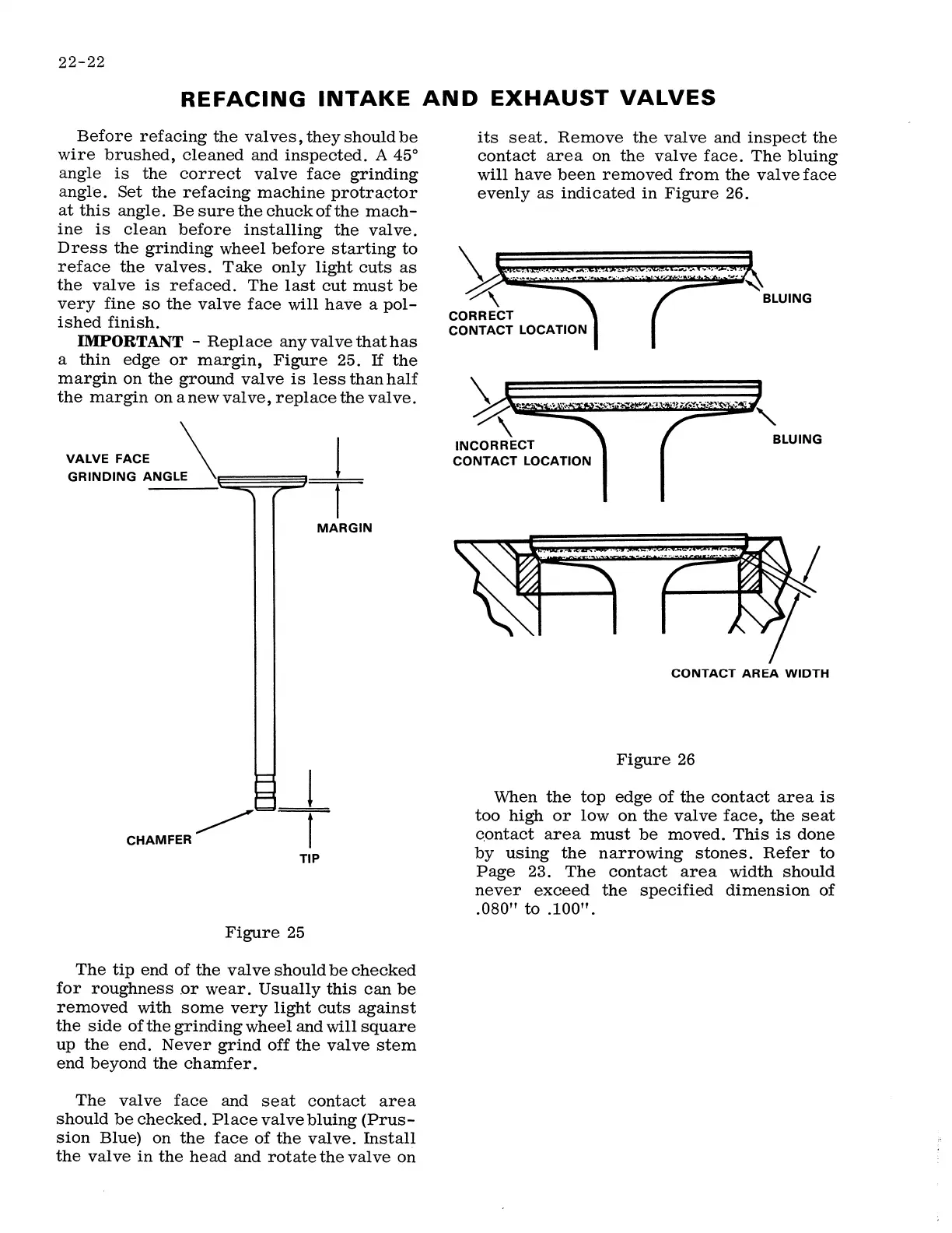
The valve face and seat contact area
should be checked. Place valve bluing (Prus-
sion Blue) on the face of the valve. Install
the valve in the head and rotate the valve on
its seat. Remove the valve and inspect the
contact area on the valve face. The bluing
will have been removed from the valve face
evenly as indicated in Figure
26.
\
CORRECT
CONTACT LOCATION
\ £=====-==-=-==-=-=_
=_ =_=_=I__,,,
\
INCORRECT
CONTACT LOCATION
BLUING
CONTACT AREA WIDTH
Figure
26
When the top edge of the contact area is
too high or low on the valve face, the seat
c.ontact area must be moved. This is done
by using the narrowing stones. Refer to
Page
23.
The contact area width should
never exceed the specified dimension of
.080"
to .100".
 Loading...