Sample Sound Input Circuit
VC
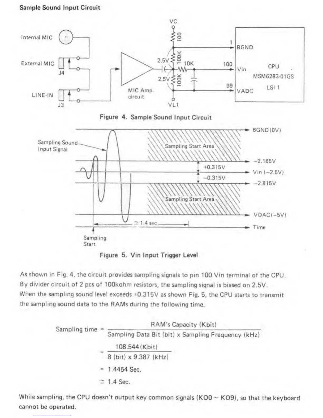
Figure 4. Sample
Sound Input
Circuit
Sampling
Start
Figure
5.
Vin
Input
Trigger Level
As shown In Fig.
4,
the circuit
provides sampling signals
to pin 100 Vin terminal of
the CPU.
By divider
circuit of
2
pcs of lOOkohm
resistors, the sampling signal
is biased on 2.5V.
When the sampling
sound
level
exceeds ±0.3
t5V as shown Fig.
5,
the CPU
starts to transmit
the
sampling sound
data to
the
RAMs during the following
time.
Sampling time
RAM's Capacity
(Kbit)
Sampling Data Bit
(bit) x Sampling Frequency (kHz)
108.544(Kbit)
8
(bit) X 9.387 (kHz)
s
1.4454 Sec.
s
1.4
Sec.
While sampling, the
CPU doesn't output key
common signals
(KOO
~
K09), so that the keyboard
cannot
be operated.
 Loading...