CIRCUIT
DESCRIPTION
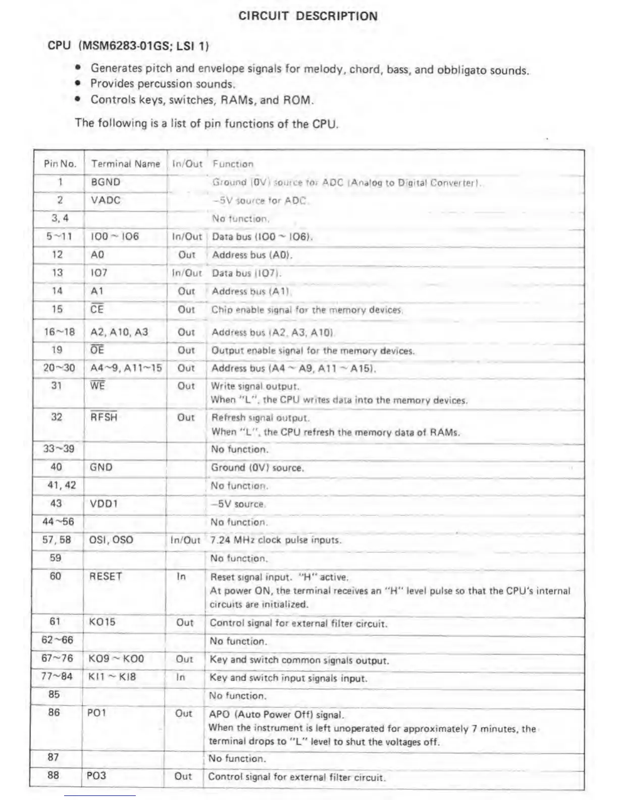
CPU (MSM6283
01GS; LSI Y)
•
Generates pitch
and
envelope
signals for melody,
chord,
bass, and obbligato
sounds.
•
Provides
percussion sounds.
•
Controls keys, switches,
RAMs, and ROM.
The
following is a list of
pin functions
of
the
CPU.
PinNo. Terminal Name In/Out Functkon
1 BOND Ground iOV) source ror AOC iAnalog
to Dignal Converter)
2
'
VAOC
*
-5V
source tor
AOC
3.4
T
No fur^citon.
5-11
1
100-106
»
In/Out Data bus
<100-
106).
"^12
’
AO Out .
Address
bus (AO).
13
:
107
•
*
1
m/Out Data bus
(107).
14 A1
1
Out Address bus (A1).
is’
'
CE
¥ ^
'
Out Chip enable sigr>al
for
the memory
devices.
16-18
A2. A10.
A3
T
•
Out
Address
bus <A2, A3. A 10).
19
idE
•
«
Out Output enable signal for the memory devices.
^20-30
I
A4-9. All-15 Out Address bus (A4
-
A9, A1
1
-
A15).
A
”
’31*
*
I
wt
W
w
Out Write signal output.
1
When
"L".
the CPU writes
data
into
the memory
devices.
32
1
RPSH
1
Out
Refresh signal
output.
When
'X*'. the CPU
refresh
the memory data of RAMs.
~33-39 f
r~
No
function.
40
[gno
^
Ground
(OV) source.
“‘41.42*
r
1
No function.
43
VDD1
1
1 -5V
source.
“44-66*”
No function.
"stTbs
”
,
OSI.OSO
'
Irt/Out 7.24
MHz clock pulse inputs.
59
'
1
» —
1
No function.
60
1
1
RESET In
Reset signal input. "H" active.
At power
ON,
the terminal receives art
''H"
level pulse so that the
CPU's
internal
[
circuits
are initialized.
61 ‘k015
1
t
Out |~Control
signal for external
filter circuit.
“62-66“^
No
function.
~67-76“
K09
-
KOO Out
^
Key ar>d
switch common signals
output.
77~84
1
KI1 -kl8 In
Key and switch input signals
input.
85
No function.
86 *P01
*
j
Out
APO
(Auto Power Off) signal.
When the
instrumertt is left
unoperated for approximately
7
minutes,
the
terminal
drops to
"V
level
to shut the voltages off.
87 1
. No function.
88 P03
r
Out
'
Control
signal for external
filter circuit.
 Loading...