— 10 —
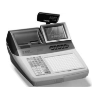
4. Remove five connectors. (CN17, CN18, CN19, CN21, CN22)
Remove the screws and the earth cable.
■ LCD ASS’Y
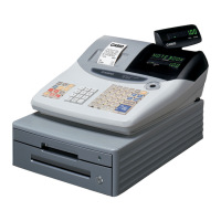
1. Remove the three screws.
Remove the mode key cover.
2. Remove the hinge cover.
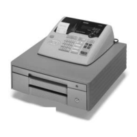
3. Remove the three screws and two FPCs.
Remove the display case.
CN19
CN18
CN22
CN17
CN21
Mode key cover
Display case