Page 2 of 14 EQ2006 R.1.5 Rev. 02 dated 09/11/2007
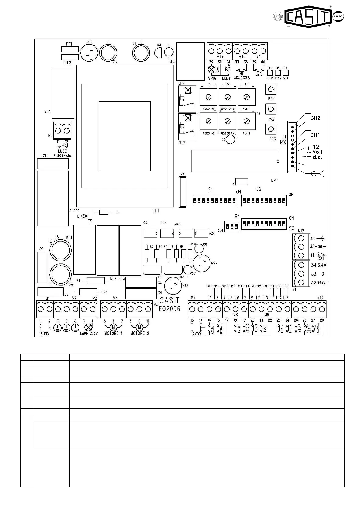
1) ELECTRIC CONNECTIONS
PLUG
Net feeding 230V (obligatorily respect the connections: neutral to the clamp 1, phase to the clamp 2).
M2
TERRA G
3 fixed clamps with the symbol of grounf for line and motors.
Output signal clinking 230V.
M4
5-6-7
Output motor 1 (delayed in closing ). Pedestrian leaf. Opening to the clamp 5, common to the clamp 6, closing
to the clamp 7.
M5
8-9-10
Output motor 2 (delayed in closing ).. Opening to the clamp 8, common to the clamp 9, closing to the clamp
10.
Light of courtesy, clean contact N.O. max.230V 4 Amp (see S3, dip 8).
M7
Output 12Vdc, max. 200 mA.
14-15
Input N.C. SAFETY EDGE 1.
•
In opening it arrests the movement, in closing it reverses the sense of march for 2" with operation type A.
(S3, dip 3 OFF).
• It always reverses the sense of march for 2" in the operation type B (S3, dip 3 ON).
14-16
Input N.C. SAFETY EDGE 2.
• In opening it reverses the sense of march for 2", in closing it arrests the movement with operation type A
(S3, dip 3 OFF).
• Input N.O. of REARMAMENT.
It becomes the input of rearmament of the control panel after the intervention of Safety edge 1 in the operation
type B (S3, dip 3 ON).