EasyManua.ls Logo

Castle Creations Phoenix-45 - User Manual

Castle Creations Phoenix-45
6 pages
Print Icon
To Next Page IconTo Next Page
Loading...
PHO
PHOPHO
PHOENIX
ENIXENIX
ENIX-
--
-45
4545
45
By
Castle Creations
45 amp Brushless Sensorless Speed Control
PHOENIX-45™ User Guide Page 1 of 6 Rev 5-date 09/01/04
This document, Phoenix-45™ software, and Phoenix-45™ PCB layout are all Copyright 2002-2003 by Patrick del Castillo and
Castle Creations
Warning!
High power motor systems can be very dangerous! High currents can heat wires and
batteries, causing fires and burning skin. Follow the wiring directions carefully! Model aircraft
equipped with high power motors can kill. Always fly at a sanctioned field. Never fly over or near
spectators. Even though this controller is equipped with a safety arming program, you should still use
caution when connecting the main battery.
1.0 Features of the Phoenix-45™:
Extremely Low Resistance (.0026 ohms)
High rate adjustable switching (PWM)
Up to 45 amps continuous current with proper air flow, 60
amps surge
Five to ten cells with four micro servos
Up to twelve cells with three micro servos
Sixteen cells MAX (with BEC disabled)
Dynamic braking ensures folding props fold promptly
BEC (3A) provides power to receiver and servos -
eliminates separate receiver battery
User Programmable Features:
Low-voltage cutoff
Over-current Protection
Brake Type
Throttle Range – fixed/self-adjusting/governor
Timing Advance
Cutoff Type
Soft Start ramp up
Switching Frequency
Runs motor in forward OR reverse
Auto Motor Cutoff with Reset
Safe “power on” arming program ensures motor will not
accidentally turn on
Low torque “soft start” prevents damage to fragile
gearboxes
Auto shut down when signal is lost or radio interference
becomes severe
2.0 Wiring Your Phoenix-45™:
Tools required:
Wire cutters Wire strippers (optional) Soldering Iron (25-40)
Parts required:
Solder (rosin core “electronic” solder) Battery connector
2.1 Servo Ratings with BEC Enabled
Servo Type 5-6 cells 7-8 cells 9-10 cells 11-12 cells
Standard (micro) servos 5 5 4 3
High Torque servos 4 4 3 2
2.2 Adding the Battery Connector
The battery connector is attached to the side of the controller that has only two power wires, and also has the
radio connector. Cut the wires to the length you require on the battery side. Strip off of the wire insulation to
expose just enough wire to attach the battery connector. (Note: if you do not have a pair of wire strippers,
you can use a modeling knife to carefully cut through the insulation around the wire. Then the insulation
should easily pull off the wire.) Attach the battery connector to the wires ENSURING THAT THE
POLARITY (red wire to battery red wire, black wire to battery black wire) IS CORRECT, following the
instructions for the battery connector.
IMPORTANT NOTE: YOU MUST BE SURE THAT THE POLARITY IS CORRECT WHEN
CONNECTING THE SPEED CONTROLLER. Incorrect polarity could permanently damage the controller.
2.3 Connecting the Motor
The motor is connected to the side of the controller that has THREE power wires. Cut the wires to the length
you require on the motor side. DO NOT CUT the wires leading from the motor. Strip the wire insulation to
expose just enough wire to solder the wires to the motor terminals. There should be three wires extending
from the motor. Connect the three speed control wires to the three motor wires. Align the wires carefully
and solder to the motor wires. Ensure that all connections (battery and motor) are correctly polarized.
2.4 Reversing Rotation
Bench test the motor connections noting the rotation of the motor. To change the rotation of the motor, swap
ANY two motor wire connections.
Battery Connector Phoenix-45™ Motor
Fig 1: Motor wiring diagram
2.5 Connecting the Receiver
Connect the receiver lead (the three color twisted wires with a connector on the end) to the throttle channel
on your receiver (usually channel 3). Do not connect a battery to the receiver, as the Phoenix-45™ will
supply power to the receiver and servos through the receiver connector. If you are using more than ten cells,
you must use a separate receiver battery. See the section 4.0 (under the heading BEC) for instructions on
disabling the BEC to use a separate receiver battery.
Older AirTronics systems require a minor change to the wiring in the receiver connector supplied with the
speed controller. Reverse the red (power) and brown (ground) wires in the connector plug so that the plug is
orange/brown/red. Use a knife blade to lift the retention tabs on the connector plug to remove the red and
brown wires. Insert the wires back into the plug and press down the retention tab.
3.0 Flying with Your Phoenix-45™:
ALWAYS PERFORM A RANGE CHECK BEFORE FLYING WITH ANY NEW SPEED
CONTROLLER! PERFORM YOUR RANGE CHECK AT FULL THROTTLE, HALF THROTTLE
AND NO THROTTLE.
Initialization sequence:
1. Connect the speed controller receiver connector to the proper channel on your receiver (usually channel 3)
2. Turn on your transmitter.
3. Connect the main power battery to the speed controller.
4. The speed controller will remain disarmed (will not operate) until it sees more than four seconds of
“brake” throttle. Move the throttle arm to the lowest position on your transmitter, wait at least four
seconds, and then test the controller to make sure that the throttle operates.
5. Go fly!
6. If the BEC cutoff occurs before you land, you may restart the motor and use low throttle if necessary by
moving the throttle stick all the way down (to the brake position) and then throttling back up. BEC cutoff
will occur again if the voltage drops too low.
Phoenix-45™
Question and Answer IconNeed help?

Do you have a question about the Castle Creations Phoenix-45 and is the answer not in the manual?

Summary

Features of the Phoenix-45

Wiring Your Phoenix-45

Adding the Battery Connector

Attach the battery connector to the controller's power wires, ensuring correct polarity.

Connecting the Motor

Connect the three motor wires to the controller's three motor terminals, ensuring correct polarity.

Reversing Rotation

Change motor rotation by swapping any two motor wire connections.

Connecting the Receiver

Connect the receiver lead to the throttle channel on your receiver.

Flying with Your Phoenix-45

Using the Features of Your Phoenix-45

Troubleshooting

Contact; Warranty Information

Phoenix-45 Programming Features

Entering Programming Mode

Verify Normal Operation

Verify the Phoenix-45 operates normally with your transmitter before programming.

Enter Programming Mode

Follow specific steps involving transmitter stick movements to enter programming mode.

Programming the Phoenix-45

Programming Setting 1 - Cutoff Voltage

Set the low voltage cutoff point based on battery type and cell count.

Programming Setting 2 - Current Limiting

Programming Setting 3 - Brake Type

Programming Setting 4 - Throttle Type

Programming Setting 5 - Electronic timing advance

Programming Setting 6 - Cutoff Type

Programming Setting 7 - Soft Start

Programming Setting 8 - PWM Switching Rate

Overview

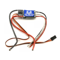
The Phoenix-45™ is a 45-amp brushless sensorless speed control designed for model aircraft. It offers a range of features for precise motor control and user-programmability, making it suitable for various applications.

Function Description

The primary function of the Phoenix-45™ is to regulate the speed of a brushless motor in model aircraft. It achieves this through adjustable switching (PWM) and can handle continuous currents up to 45 amps (with proper airflow) and surges up to 60 amps. The device is compatible with battery configurations ranging from five to ten cells for four micro servos, or up to twelve cells for three micro servos. For configurations exceeding sixteen cells, the Battery Eliminator Circuit (BEC) must be disabled, requiring a separate receiver battery.

A key safety feature is the "Safe Power Up" arming program, which prevents accidental motor starts. The controller will not arm until the transmitter throttle stick has been held in the "Brake" position (all the way down) for at least four seconds. Once armed, the LED provides visual confirmation that the controller is ready.

The Phoenix-45™ includes a BEC that supplies power to the receiver and servos, eliminating the need for a separate receiver battery in most setups. However, for setups using more than twelve cells, the BEC must be disabled by cutting the red wire in the receiver connector trio and insulating it.

The device also incorporates a motor cutoff feature that activates when the input battery voltage drops below a programmed cutoff voltage (factory preset at 5.0V) for more than half a second. This protects the aircraft from loss of control due to low receiver voltage. After a cutoff, the motor can be restarted at low throttle by moving the throttle to the braking position. Additionally, motor cutoff will occur if the transmitter signal is lost or if there is excessive radio noise, and can be re-established by moving the throttle to the braking position for one second.

Usage Features

The Phoenix-45™ offers extensive user-programmable features, allowing customization for different flight conditions and motor types. These features include:

  • Low-voltage cutoff: Users can set the cutoff voltage to protect batteries and ensure safe operation. Options range from 4.0V for 5-cell NiCad/NiMH packs to 12.0V for 16-cell NiCad or 4-cell Lithium packs. When setting LiPo cutoff voltage, users should follow their battery manufacturer's recommendations.
  • Over-current Protection (Current Limiting): This feature describes how the controller reacts to an over-current condition. Options range from "Very sensitive" (rapid shutdown at very low over-current threshold) to "Over current disabled" (no detection). Users are advised to change this setting at their own risk, as damage due to over-current is not covered by the manufacturer's warranty.
  • Brake Type: The Phoenix-45™ supports various brake types. "Soft delayed brake" (4-second delay) is recommended for general aircraft with fixed or folding props. "Hard delayed brake" is for direct drive applications needing more braking power. "Soft brake, no delay" and "Hard brake, no delay" are for competition use requiring short brake delays. "Brake Disabled" is an option for helicopters. Dynamic braking ensures folding props fold promptly.
  • Throttle Range: The controller supports "fixed," "self-adjusting," and "governor" throttle modes. "Auto Calibrating throttle" is recommended for general aircraft, while "Fixed throttle" is for fixed-pitch helicopters. "Governor Mode" (Low or High RPM Range) is recommended for collective pitch helicopters. In Governor Mode, throttle stick position determines the RPM, and the controller attempts to maintain it regardless of load changes. Brake is always disabled in Governor Mode.
  • Timing Advance (Electronic timing advance): This feature allows users to adjust the motor timing for optimal performance. Options include "High advance timing" (12°-35°) for higher pole count motors (e.g., Jeti, large Mega motors) for more power, "Standard advance timing" (5°-20°) for most motors (e.g., Aveox, Hacker, Astro, smaller Mega, Kontronik) for a good balance of power and efficiency, and "Low advance timing" (0°-15°) when efficiency or run-time is a primary concern. The controller automatically senses motor type by inductance and sets the maximum advance accordingly.
  • Cutoff Type: Users can choose between "Hard Cutoff" (immediate motor shutdown) or "Soft Cutoff" (throttle down at low voltage or over-current).
  • Soft Start ramp up: This feature controls the motor's initial spool-up speed. Options include "Very soft start" (recommended for fragile gearboxes; governor mode slowest spool up), "Soft Start" (recommended for most setups; governor mode soft start, slow spool up), and "Fast start" (recommended for fastest startup; governor mode faster start, fast spool up).
  • Switching Frequency (PWM Switching Rate): Options include 11 KHz (recommended for most brushless motors), 22 KHz (recommended for low inductance motors), and 41 KHz (recommended for very low inductance motors).

Programming the Phoenix-45™ is interactive, using the LED to flash setting numbers and values. Users respond by moving the transmitter stick to "yes" (full "On" throttle) or "no" (full "Off" throttle) for about 5 seconds. The LED flashes rapidly to confirm acceptance, and then the throttle stick is moved to the middle position to confirm readiness for the next question. Users can choose to program only specific features by disconnecting power after storing desired settings.

Maintenance Features

The Phoenix-45™ is designed for durability, but proper installation and usage are crucial for its longevity. Users are advised to:

  • Perform a range check: Always perform a range check at full, half, and no throttle before flying with any new speed controller.
  • Ensure correct polarity: Incorrect polarity when connecting the speed controller can permanently damage the device.
  • Monitor battery voltage: Repeatedly restarting the motor after a cutoff can drain the battery to a point where the radio receiver stops operating, leading to a loss of control. If the controller cuts off with fresh batteries, it indicates the motor is drawing too much current, suggesting the use of a smaller prop or higher-rated batteries.
  • Check connections: If the receiver and servos are dead, ensure all connections are correct and polarized.
  • Troubleshooting: If the throttle does not work, ensure the controller is arming by holding the throttle stick all the way down with trim down for four seconds. If it still doesn't arm, reversing the throttle control on the transmitter may be necessary. Also, check endpoint adjustments on the radio.

The Phoenix-45™ is warranted for one year from the date of purchase against manufacturing and component defects. This warranty does not cover abuse, neglect, or damage due to incorrect wiring, over-voltage, or overloading.

Castle Creations Phoenix-45 Specifications

General IconGeneral
TypeBrushless ESC
Continuous Current45A
Burst Current60A
BrakeYes
ReversibleYes
ProgrammableYes
Input Voltage2-3S LiPo
Cells2-3 LiPo
BEC Output5V / 3A
ProgrammingCastle Link

Related product manuals