Do you have a question about the Castle Creations Phoenix-80 and is the answer not in the manual?
Details servo compatibility based on cell count and BEC usage.
Instructions for connecting the battery connector to the speed controller.
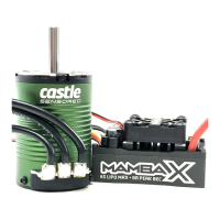
How to connect the motor wires to the speed controller.
Method to change motor rotation direction by swapping wires.
How to connect the receiver lead to the throttle channel.
Explanation of BEC power supply and how to disable it.
How the brake function is activated via the throttle stick.
Details on motor cutoff due to low voltage or signal loss.
Describes the safety feature preventing accidental motor start-up.
Function of the LED for programming and full throttle indication.
Troubleshooting steps when the throttle is unresponsive or the controller won't arm.
Diagnosing motor cutoff issues, often related to battery voltage.
Verifying normal operation before entering programming mode.
Step-by-step instructions to enter the programming mode.
Guide to setting the low-voltage cutoff for the battery.
Configuration of the controller's reaction to over-current conditions.
Selection of different brake types and their applications.
Options for throttle control modes, including governor.
Adjusting electronic timing for motor performance and efficiency.
Choosing between hard or soft motor cutoff upon voltage issues.
Setting the initial motor spool-up speed for smoother acceleration.
Selecting the PWM switching frequency for motor operation.
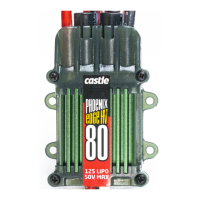
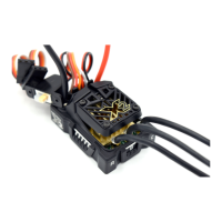
The Phoenix-80™ is an 80-amp brushless sensorless speed control designed for model aircraft. It offers a range of features for precise motor control and user customization, while also incorporating safety mechanisms to prevent accidental operation and damage.
The primary function of the Phoenix-80™ is to regulate the speed of a brushless sensorless motor in model aircraft. It achieves this through high-rate adjustable switching (PWM), allowing for efficient power delivery. The device is capable of handling continuous currents up to 80 Amps with adequate airflow and surge currents up to 120 Amps. It supports a wide range of battery configurations, from 5 to 20 cells, with varying servo support depending on the cell count. For setups exceeding 10 cells, disabling the internal Battery Eliminator Circuit (BEC) and using a separate receiver battery is recommended.
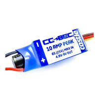
The Phoenix-80™ includes a BEC that provides 3 Amps of power to the receiver and servos, eliminating the need for a separate receiver battery in most configurations. This integrated power supply simplifies wiring and reduces overall weight.
A key feature is its user-programmable settings, which allow for extensive customization to suit different aircraft types and flying styles. These settings include:
The Phoenix-80™ also features an auto motor cutoff with reset, allowing the motor to be restarted at low throttle after a cutoff event. A "safe power on" arming program prevents accidental motor startup, requiring the transmitter stick to be held at the "Brake" position for at least four seconds before the controller arms. This ensures the motor will not turn on inadvertently. An LED indicator provides visual feedback for programming and indicates when full throttle has been reached.
Connecting the Phoenix-80™ involves three main steps: motor connection, battery connection, and receiver connection.
Before flying, a range check is crucial, performed at full throttle, half throttle, and no throttle. The initialization sequence involves connecting the receiver, turning on the transmitter, connecting the main battery, and then moving the throttle arm to the lowest position for at least four seconds to arm the controller. The controller will remain disarmed until it detects this "brake" throttle position.
Programming the Phoenix-80™ is an interactive process guided by the LED. The controller flashes a setting number, followed by possible setting values. Users respond by moving the transmitter stick to "yes" (full "On" throttle) or "no" (full "Off" throttle) for about 2 seconds. The LED flashes rapidly to confirm acceptance of the answer. After the rapid flash, the throttle stick is moved to the middle position to confirm readiness for the next question. Users can choose to program only specific features by disconnecting power after making desired changes; remaining settings will retain their previous values.
The Phoenix-80™ is designed for durability, but proper usage and care are essential for its longevity.
The manual emphasizes that high-power motor systems can be very dangerous, capable of causing fires, burns, and even fatalities. Users are advised to follow wiring directions carefully, fly at sanctioned fields, and never fly over or near spectators. Despite the safety arming program, caution is always necessary when connecting the main battery.
| Type | Brushless ESC |
|---|---|
| Continuous Current | 80A |
| Low Voltage Cutoff | Adjustable |
| Thermal Protection | Yes |
| Burst Current | 100A |
| Input Voltage | 2-6S LiPo |
| BEC Current | 5A |
| Programming | Castle Link |
| PWM Frequency | 8 kHz |