Do you have a question about the CAT Pumps 1530 and is the answer not in the manual?
Covers hazards like flammable liquids, electrical shock, rotating parts, hot surfaces, skin puncture, and pumping liquids.
Procedures for removing discharge and inlet manifolds and seals.
Steps for disassembling and reassembling seals and related components.
Steps for taking apart and putting back together plungers and retainers.
Procedures for removing valve assemblies and their components.
Steps for correctly reassembling valve components.
Checking oil seals, covers, drain plugs, and oil level for leaks or wear.
Details on required torque values and tightening sequences for pump components.
List of technical bulletins with subject and applicable pump models.
Guide to identifying probable causes and solutions for common pump issues.
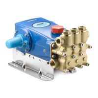
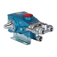
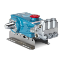
The provided document is a service manual for Cat Pumps' 15 & 25 Frame Plunger Pumps, offering comprehensive guidance on their function, usage, and maintenance. These pumps are designed for various high-pressure applications, emphasizing product quality, reliability, and support.
Cat Pumps' 15 & 25 Frame Plunger Pumps are positive displacement pumps engineered to deliver liquids at high pressure. The core function involves plungers reciprocating within seal chambers to create pressure, moving the fluid through inlet and discharge manifolds. The design incorporates a crankcase, which houses the crankshaft and connecting rods, converting rotational motion into the linear motion of the plungers. Valves, including both inlet and discharge valves, control the flow direction of the liquid, ensuring efficient pumping. The pumps are built to handle a range of liquids, though specific precautions are necessary for flammable, explosive, hot, chemical, or hazardous fluids. The system relies on proper lubrication of drive-end components with genuine Cat Pumps custom-blend hydraulic oil to ensure longevity and prevent damage. Pulsation dampeners, when used, require nitrogen charging to prevent explosions. The overall design aims for robust performance in demanding high-pressure environments.
The pumps are designed for operation within specified parameters to ensure safe and effective use. Users must adhere to maximum recommended RPM, pressure, and temperature limits as outlined in the individual pump data sheet and service manual. Proper installation of fittings, pipes, and hoses, ensuring they are correctly sized, connected, and rated for the maximum pressure and flow, is crucial to prevent personal injury and property damage. All connections must be tight and secure, with PTFE thread tape or pipe thread sealant applied sparingly to prevent lodging in the pump.
For electrical safety, the pump and associated equipment should never be serviced while energized. "Lock Out" and "Tag Out" procedures must be followed, and power and water supplies turned off before any service. For mobile equipment, engines and hydraulics must be turned off and secured. Safety guards on belt drives, couplings, and shafts are mandatory during operation to protect against rotating parts hazards.
The pump's crankshaft rotation direction is critical; it should turn towards the manifold head, with the oil level visible at the center red dot on the sight gauge. Reverse rotation can lead to improper lubrication and damage. Excessive belt tension should also be avoided as it can damage bearings and reduce horsepower.
Bypass operation for extended periods is discouraged due to potential heat build-up, which can damage the pump. If bypass is necessary, the line should route to a supply reservoir of cool water or use a thermo valve/auto shut-off assembly to manage temperature. Dry operation (without water or liquid) must be avoided, as it can cause significant damage. All inlet valves must be open before starting, and the inlet feed must exceed the maximum flow delivered by the pump.
When using high-pressure guns, the safety trigger lock should be engaged when not in use to prevent accidental operation. Hands should never be used to check for leaks; cardboard is recommended. Adequate safety equipment, including clothing, masks, goggles, and eye protection, is essential when operating high-pressure sprayers. For hazardous liquids, a Safety Data Sheet (SDS) should be consulted, and appropriate safety measures taken, including providing guards or shields for personnel protection.
The service manual provides detailed instructions for disassembly, reassembly, and inspection of key pump components, including seals, plungers, valves, and the crankcase. A preventive maintenance schedule outlines daily, weekly, 50-hour, 500-hour, 1500-hour, and 3000-hour checks for various components.
Seal Servicing: This involves removing both discharge and inlet manifolds. Low-pressure and high-pressure seals, V-packings, male and female adapters, spacers, O-rings, and backup rings are inspected for wear, scale build-up, cuts, or deterioration and replaced as needed. Special attention is given to gently driving seals into position to avoid damage. Liquid gasket application is recommended for O-ring crevices and seal surfaces in certain applications, and silicone-based lubricant is specified for EPDM elastomers.
Plunger Servicing: After manifold removal, plunger retainers, O-rings, backup rings, gaskets, ceramic plungers, barrier slingers, and keyhole washers are disassembled. Components are inspected for wear, scoring, chips, or cracks. Ceramic plungers are installed in one direction without force. Wicks should not be lubricated at initial start-up, allowing grease from low-pressure seals to penetrate the plunger surface over 10-15 minutes of operation.
Valve Servicing: This involves removing valve plugs, spring retainers, springs, valves, seats, O-rings, and backup rings. Components are examined for internal wear, breaks, fatigue, grooves, or pitting and replaced as necessary. Proper assembly sequence, including O-ring and backup ring placement, and correct orientation of the valve (dish side down) are emphasized.
Crankcase Servicing: The crankcase oil seals are inspected for leaks and wear. Checks for leaks at the rear cover, drain plug, bubble gauge, and dipstick are recommended. Oil level and evidence of water in the oil should be checked regularly, with oil changes performed on a scheduled basis (initial change after 50 hours, then every 500 hours). The crankshaft should be rotated by hand to ensure smooth bearing movement, and crankshaft oil seals inspected externally for drying, cracking, or leaking. For certain models, liquid gasket application is specified for the crankshaft seal, bearing cover, or rear cover to maintain a moisture-free seal.
Torque Specifications and Sequences: The manual includes a detailed torque chart for various pump items (plunger retainers, manifold screws, valve plugs, etc.) and specific torque sequences for multi-fastener components like manifolds, ensuring even pressure distribution and preventing damage. Antiseize lubricant is highly recommended for stainless steel components to prevent galling.
Troubleshooting: A "Diagnosis and Maintenance" section provides a comprehensive list of common problems (e.g., low pressure, pulsation, water leak, knocking noise, oil leak, rough running, premature seal failure), their probable causes, and corresponding solutions. This includes checking for worn nozzles, air leaks, clogged filters, worn seals, damaged bearings, and improper inlet conditions.
Overall, the manual emphasizes the importance of regular inspection, timely replacement of worn components, and adherence to specified procedures and safety guidelines to ensure the longevity, reliability, and safe operation of Cat Pumps' 15 & 25 Frame Plunger Pumps.
| Model | 1530 |
|---|---|
| Pump Type | Triplex Plunger Pump |
| Inlet Port Size | 1/2" NPTF |
| RPM | 1450 RPM |
| Pump Model Series | 1500 Series |
| Temperature Range | Up to 140°F |
| Outlet Port Size | 3/8" NPT |
| Discharge Port Size | 3/8" NPT |
| Inlet Size | 1/2" NPT |
| Outlet Size | 3/8" NPT |
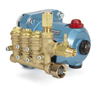
| Material | Brass Manifold |