PN 30263 Rev C 11709
WARNING
All systems require both a primary pressure regulating device (i.e., regulator, unloader) and a secondary pressure safety relief device (i.e., pop-off valve, safety valve).
Failure to install such relief devices could result in personal injury or damage to the pump or to system components. CAT PUMPS does not assume any liability or responsibility
for the operation of a customer’s high pressure system.
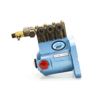
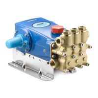
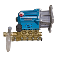
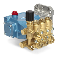
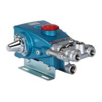
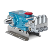
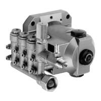
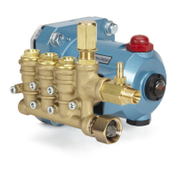
1DX, 2DX, 3DX, 3DNX, 3SP, 3SPX PLUNGER PUMP SERVICE MANUAL
®
SPECIFICATIONS: Maximum specifications refer to individual attributes. It is
not implied that all maximums can be performed simultaneously. If more
than one maximum is considered, check with your CAT PUMPS supplier to
confirm the proper performance and pump selection. Refer to individual Data
Sheets for complete specifications, parts list and exploded view.
LUBRICATION: Fill crankcase with special CAT PUMP Hydraulic oil per pump
specifications [1DX, 2DX, 3DX, 3DNX-8.5 oz., 3SP, 3SPX-10.15 oz.]. DO NOT
RUN PUMP WITHOUT OIL IN CRANKCASE. Change initial fill after 50 hours
running period. Thereafter, change oil every 3 months or 500 hour intervals.
DRIVE SELECTION: The pump shaft size is 5/8" hollow shaft on “ES” and
“ELS” models, 3/4" hollow shaft on “GEI” and “GS” models, 1" hollow shaft on
“G1I” models. The motor or engine driving the pump must be of adequate
horsepower to maintain full RPM when the pump is under load. Select the
horsepower requirement according to required pump discharge flow and maxi-
mum pressure at the pump! Consult the manufacturer of gas or diesel engine
for proper selection.
MOUNTING: 1DX, 2DX, 3DX, 3DNX, 3SP and 3SPX models are direct drive.
The 1DX.MIST and 2DX.MIST electric models can be mounted directly to a
C-Face motor; the
3SP35GEI and 3SPX35GEI models come with an adapter
plate to mount to a C-Face motor. The gas model comes with an adapter plate
that mounts to a gas engine. Before mounting pump to electric motor or gas
engine, apply PN 6106 antiseize lubricant to pump shaft. Refer to Technical
Bulletin 055 for instructions on removing pump from electric motor or gas
engine. To minimize piping stress, use appropriate flexible hose to inlet and
discharge ports.
LOCATION: If the pump is used in extremely dirty or humid conditions, it is
recommended pump be enclosed. Do not store or operate in excessively high
temperature areas or enclosed without proper ventilation. Temperatures above
130°F are permissible. Add 1/2 PSI inlet pressure per each degree F over
130°F. Elastomer or RPM changes may be required. See Tech Bulletin 002 or
call CAT PUMPS for recommendations.
INLET CONDITIONS: Refer to complete Inlet Condition Check-List in this
manual before starting system. DO NOT STARVE THE PUMP OR RUN DRY.
DISCHARGE CONDITIONS: OPEN ALL VALVES BEFORE STARTING
SYSTEM to avoid deadhead overpressure condition and severe damage to the
pump or system.
A reliable Pressure Gauge should be installed near the discharge outlet of the
high pressure manifold.
This is extremely important for adjusting pressure
regulating devices and also for proper sizing of the nozzle or restricting orifice.
The pump is rated for a maximum pressure; this is the pressure that is read at
the discharge manifold of the pump, NOT AT THE GUN OR NOZZLE.
Use PTFE thread tape or pipe thread sealant (sparingly) to connect accessories
or plumbing. Exercise caution not to wrap tape beyond the last thread to avoid
tape from becoming lodged in the pump or accessories. This condition will
cause a malfunction of the pump or system.
PRESSURE REGULATION: All systems require both a primary pressure
regulating device (i.e., regulator, unloader) and a secondary pressure safety
relief device (i.e., pop-off valve, safety valve). The primary pressure device
must be installed on the discharge side of the pump. The function of the primary
pressure regulating device is to protect the pump from over pressurization,
which can be caused by a plugged or closed off discharge line. Over pressur-
ization can severely damage the pump, other system components and can
cause bodily harm. The secondary safety relief device must be installed
in-line between the primary device and pump or on the opposite side of the
manifold head. This will ensure pressure
relief of the system if the primary
regulating device fails. Failure to install such a safely device will void the warranty
on the pump.
NOZZLES: A worn nozzle will result in loss of pressure. Do not adjust pressure
regulating device to compensate. Replace nozzle and reset regulating device
to system pressure.
PUMPED LIQUIDS: Some liquids may require a flush between operations
or before storing. For pumping liquids other than water, contact your CAT
PUMPS supplier.
STORING: For extended storing or between use in cold climates, drain all
pumped liquids from pump and flush with antifreeze solution to prevent
freezing and damage to the pump. DO NOT RUN PUMP WITH FROZEN
LIQUID (refer to Tech Bulletin 083).
1DX MODELS: 1DX015ELS.MIST, 1DX03ELS.MIST
2DX MODELS: 2DX20ES, 2DX27GS, 2DX30GS
2DX05ELS.MIST, 2DX15ES.MIST,
2DX20ES.MIST, 2DX27ES.MIST
2DX30ES.MIST
3DX MODELS: 3DX25GSI, 3DX27GSI, 3DX29GSI,
3DX30GSI
3DNX MODELS: 3DNX25GSI, 3DNX27GSI
3SP MODELS: 3SP30G1I, 3SP35GEI
3SPX MODELS: 3SPX30G1I, 3SPX35GEI
INSTALLATION AND START-UP INFORMATION
Optimum performance of the pump is dependent upon the entire liquid system and will be obtained only
with the proper selection, installation of plumbing, and operation of the pump and accessories.
CAT PUMPS (U.K.) LTD.
1 Fleet Business Park, Sandy Lane, Church Crookham
FLEET, Hampshire, GU52 8BF, England
Phone Fleet 44 1252-622031 — Fax 44 1252-626655
e-mail: sales@catpumps.co.uk
N.V. CAT PUMPS INTERNATIONAL S. A.
Heiveldekens 6A, B-2550 Kontich, Belgium
Phone 32- 3- 450.71.50 — Fax 32-3- 450.71.51
e-mail: cpi@catpumps.be www.catpumps.be
CAT PUMPS DEUTSCHLAND GmbH
Buchwiese 2, D-65510 Idstein, Germany
Phone 49 6126-9303 0 — Fax 49 6126-9303 33
e-mail: catpumps@t-online.de www.catpumps.de
World Headquarters
CAT PUMPS
1681 - 94th Lane N.E. Minneapolis, MN 55449-4324
Phone (763) 780-5440 — FAX (763) 780-2958
e-mail: techsupport@catpumps.com
www.catpumps.com
International Inquiries
FAX (763) 785-4329
e-mail: intlsales@catpumps.com
®
The Pumps with Nine Lives