TYPICAL RESERVOIR TANK
RECOMMENDED 6 TO 10 TIMES SYSTEM CAPACITY
1/4 5/16 3/8 1/2 5/8 3/4 1"
0.5 16 5 2
1 54 20 7 2
2 180 60 25 6 2
3 380 120 50 13 4 2
4 220 90 24 7 3
5 320 130 34 10 4
6 220 52 16 7 1
8 300 80 25 10 2
10 450 120 38 14 3
15 900 250 80 30 7
20 1600 400 121 50 12
25 650 200 76 19
30 250 96 24
40 410 162 42
50 600 235 62
60 370 93
*At a fixed flow rate with a given size hose, the pressure drop across a given hose length
will be directly proportional. A 50 ft. hose will exhibit one-half the pressure drop of a 100
ft. hose. Above values shown are valid at all pressure levels.
PRESSURE DROP IN PSI PER 100 FT OF HOSE
WITH TYPICAL WATER FLOW RATES
Hose Inside Diameters, Inches
Water*
Flow
Gal/Min
HOSE FRICTION LOSS
Water
GPM
1
2
3
5
8
10
15
25
40
60
80
100
Steel Pipe—Nominal Dia.
1/4 3/8 1/2 3/4 1 1
1
/4 1
1
/2
8.5 1.9
30 7.0 2.1
60 14 4.5 1.1
150 36 12 2.8
330 86 28 6.7 1.9
520 130 43 10 3.0
270 90 21 6.2 1.6
670 240 56 16 4.2 2.0
66 17 8.0
37 17
52 29
210 107 48
Brass Pipe—Nominal Dia.
1/4 3/8 1/2 3/4 1
1
1
/4 1
1
/2
6.0 1.6
20 5.6 1.8
40 11 3.6
100 28 9.0 2.2
220 62 21 5.2 1.6
320 90 30 7.8 2.4
190 62 16 5.0 1.5
470 150 40 12 3.8 1.7
39 11 5.0
23 11
40 19
61 28
Copper Tubing O.D. Type L
1/4 3/8 1/2 5/8 3/4 7/8
120 13 2.9 1.0
400 45 10 3.4 1.3
94 20 6.7 2.6
230 50 17 6.1 3.0
500 120 40 15 6.5
180 56 22 10
120 44 20
330 110 50
550 200 88
WATER LINE PRESSURE LOSS
PRESSURE DROP IN PSI PER 100 FEET
1/2 0.622 0.41 18.5 9.3 0.78 1.67 3.71 0.93 3.33
3/4 0.824 0.54 24.5 12.3 1.03 2.21 4.90 1.23 4.41
1 1.049 0.69 31.2 15.6 1.31 2.81 6.25 1.56 5.62
1
1
/4 1.380 0.90 41.0 20.5 1.73 3.70 8.22 2.06 7.40
1
1
/2 1.610 1.05 48.0 24.0 2.15 4.31 9.59 2.40 8.63
2 2.067 1.35 61.5 30.8 2.59 5.55 12.30 3.08 11.60
2
1
/2 2.469 1.62 73.5 36.8 3.09 6.61 14.70 3.68 13.20
3 3.068 2.01 91.5 45.8 3.84 8.23 18.20 4.57 16.40
4 4.026 2.64 120.0 60.0 5.03 10.80 23.90 6.00 21.60
Nominal
Pipe
Size
Inches
Inside
Diameter
Inches
RESISTANCE OF VALVES AND FITTINGS
Gate
Valve
Globe
Valve
Angle
Valve
45˚
Elbow
90˚
Elbow
180˚
Close
Ret
Tee
Thru
Run
Arriving at a total line pressure loss, consideration should then be given to
pressure loss created by valves, fittings and elevation of lines.
If a sufficient number of valves and fittings are incorporated in the system to
materially affect the total line loss, add to the total line length, the equivalent
length of line of each valve or fitting.
Tee
Thru
Branch
Equivalent Length of Standard Pipe in Feet
Bypass Line
(from regulator or unloader)
Level Sensing
Device
Bypass Line
(from regulator or
unloader)
MIN. 4"
1.5 x D (Min.)
Minimum Two Baffles
Sealed at Bottom
Minimum
Liquid
Level
FILTER
MIN. 4"
Flexible Hose
to Pump
Supply Line
(Dia of pipe)
T
X
D
→
→
→
→
→
→
→
→
→
Q. How can I find the RPM needed to get specific GPM
(Gallons Per Minute) I want?
Rated RPM
A. Desired RPM = Desired GPM x
Rated GPM
Q. I have to run my pump at a certain RPM. How do I figure
the GPM I’ll get?
Rated GPM
A. Desired GPM = Desired RPM x
Rated RPM
Q. Is there a simple way to find the approximate horsepower
I’ll need to run the pump?
A. Electric Brake GPM x PSI (Standard 85%
Horsepower Required
=
1460 Mech. Efficiency)
Q. What size motor pulley should I use?
Pump RPM
A. Pump Pulley (Outer Diameter) x
Motor/Engine RPM
Q. How do I calculate the torque for my hydraulic drive
system?
GPM x PSI
A. Torque (ft. lbs.) = 3.6
RPM
( )
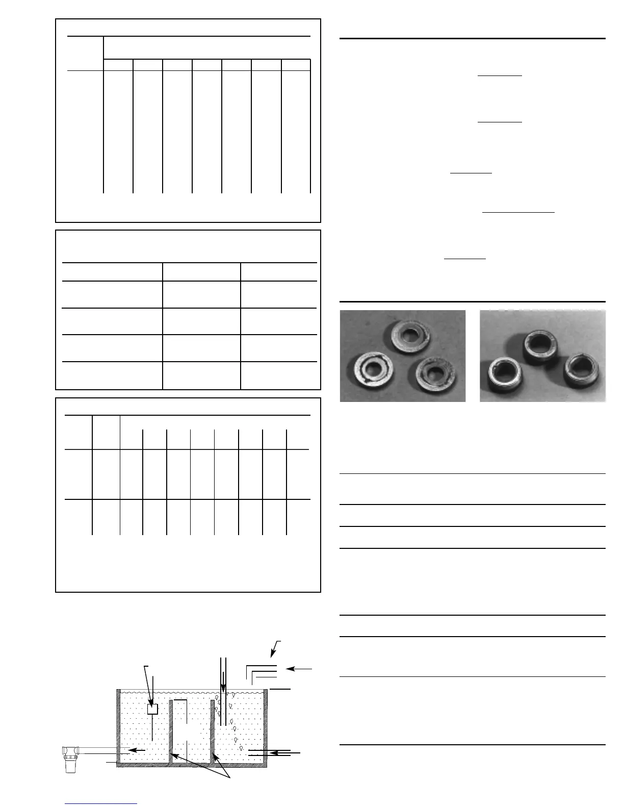
One or several of the conditions shown in the chart below may
contribute to cavitation in a system resulting in premature wear,
system downtime and unnecessary operating costs.
CONDITION SOLUTION
Inadequate inlet
●
Increase line size to the inlet port or one size
line size larger
Water hammering
●
Install C.A.T. Tube
liquid acceleration/
●
Move pump closer to liquid supply
deacceleration
Rigid Inlet Plumbing
●
Use flexible wire reinforced hose to absorb
pulsation and pressure spikes
Excessive Elbows in
●
Keep elbows to a minimum and less than 90°
Inlet Plumbing
Excessive Liquid
●
Use Thermo Valve in bypass line
Temperature
●
Do not exceed pump temperature specifications
●
Substitute closed loop with baffled holding tank
●
Adequately size tank for frequent or high
volume bypass
●
Pressure feed high temperature liquids
●
Properly ventilate cabinets and rooms
Air Leaks in Plumbing
●
Check all connections
●
Use PTFE thread tape or pipe thread sealant
Agitation in Supply
●
Size tank according to pump output —
Tank Minimum 6-10 times system GPM
●
Baffle tank to purge air from liquid and
separate inlet from discharge
High Viscosity Liquids
●
Verify viscosity against pump specifications
before operation
●
Elevate liquid temperature enough to reduce
viscosity
●
Lower RPM of pump
●
Pressure feed pump
●
Increase inlet line size
Clogged Filters
●
Perform regular maintenance or use clean
filters to monitor build up
●
Use adequate mesh size for liquid and pump
specifications
Handy Formulas to Help You
(Consult
Engine Mfr.)
Avoid Cavitation Damage
 Loading...