2. Wait for ten minutes.
Do not loosen the high pressure fuel lines in order to
remove air pressure from the fuel system.
Engine Oil
To relieve pressure from the lubricating system, turn
off the engine.
i05909227
Welding on Engines with
Electronic Controls
SMCS Code: 1000
NOTICE
Because the strength of the frame may decrease,
some manufacturers do not recommend welding onto
a chassis frame or rail. Consult the OEM of the equip-
ment or your Cat dealer regarding welding on a chas-
sis frame or rail.
Proper welding procedures are necessary in order to
avoid damage to the engine ECM, sensors, and
associated components. When possible, remove the
component from the unit and then weld the
component. If removal of the component is not
possible, the correct procedure must be followed.
When welding on a unit that is equipped with a Cat
Electronic Engine, the following is considered to be
the safest procedure:
NOTICE
Do not ground the welder to electrical components
such as the ECM or sensors. Improper grounding
can cause damage to the drive train, the bearings,
hydraulic components, electrical components, and
other components.
Do not ground the welder across the centerline of the
package. Improper grounding could cause damage
to the bearings, the crankshaft, the rotor shaft, and
other components.
Clamp the ground cable from the welder to the com-
ponent that will be welded. Place the clamp as close
as possible to the weld. This will help reduce the pos-
sibility of damage.
Note: Perform the welding in areas that are free from
explosive hazards.
1. Stop the engine. Turn the switched power to the
OFF position.
2. Disconnect the negative battery cable from the
battery. If a battery disconnect switch is provided,
open the switch.
3. Disconnect the J1/P1 and J2/P2 connectors from
the ECM. Move the harness to a position that will
not allow the harness to move back accidentally,
and contact any of the ECM pins.
4. Disconnect any component with a microprocessor
from the engine harness, such as:
• Engine ECM
• Product Link
• Cell/Sat Radio
• DOC Identity Modules
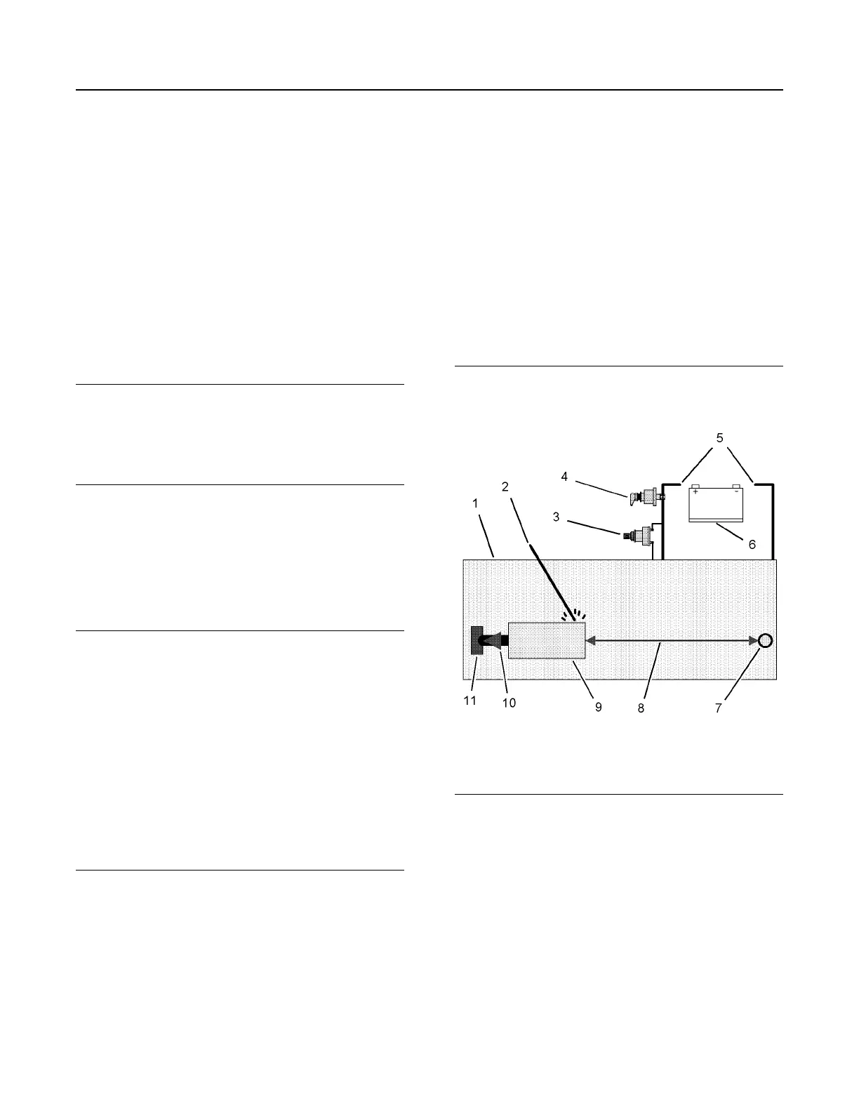
Illustration 94 g01075639
Use the example above. The current flow from the
welder to the ground clamp of the welder will not
damage any associated components.
(1) Engine
(2) Welding electrode
(3) Keyswitch in the OFF position
(4) Battery disconnect switch in the open position
(5) Disconnected battery cables
(6) Battery
(7) Electrical/Electronic component
(8) Minimum distance between the component that is being
welded and any electrical/electronic component
(9) The component that is being welded
(10) Current path of the welder
(11) Ground clamp for the welder
100
SEBU7125-13
Maintenance Section
Welding on Engines with Electronic Controls
 Loading...