into the GSC. When the engine overspeeds, the
engine overspeed indicator FLASHES. The engine is
shutdown and the engine is not allowed to start until
the fault is corrected.
Low Coolant Level – The engine coolant level drops
below the probe of the coolant loss sensor. When the
low coolant level fault occurs, the engine coolant
level indicator FLASHES. The engine is shut down.
The engine is not allowed to start until the fault is
corrected.
Overcrank – The engine does not start within the
setpoint for total cycle crank time that is programmed
into the GSC. When the overcrank fault occurs, the
overcrank indicator FLASHES. The engine is not
allowed to start until the fault is corrected.
Note: The GSC can be programmed to override the
shutdown for low oil pressure and high water
temperature faults. When the operator overrides the
shutdown faults, the GSC responds to the faults as
though the faults are alarm faults. The corresponding
dedicated shutdown indicator is ON
CONTINUOUSLY and the shut down indicator will not
be flashing. The engine continues to run and the
engine can be restarted if required. When the
dedicated shutdown indicator is ON
CONTINUOUSLY, the setpoint for shutdown has
been exceeded, but the GSC is programmed to
override the shutdown fault. The GSC does not treat
the shutdown fault as a shutdown fault. The GSC
treats the shutdown fault as an alarm fault. At the
factory, the GSC is programmed to treat a low oil
pressure fault and a high water temperature fault as
shutdown faults. The operator or the service
technician must decide to override these shutdown
faults. The operator or the service technician must
program the GSC to treat the shutdown faults as
alarm faults. For programming procedures, refer to
the Systems Operation, Testing and Adjusting,
SENR5809, “Electronic Modular Control Panel II
(EMCP II) for MUI Engines” or to the Systems
Operation, Testing and Adjusting, SENR5398,
“Electronic Modular Control Panel II (EMCP II) for
EUI Engines”.
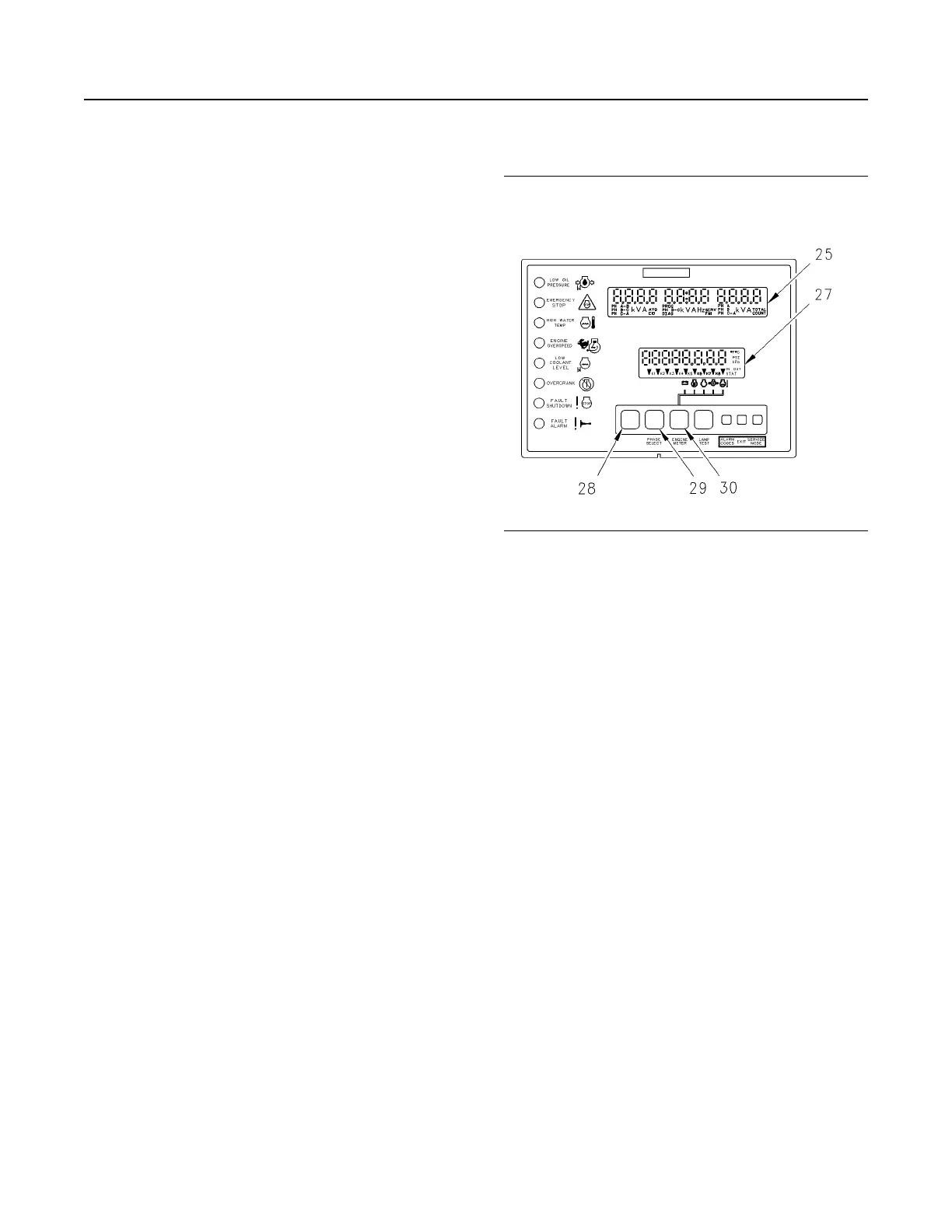
Display
Illustration 51 g00636342
Display Area of the GSC
(25) Upper display
(27) Lower display
(28) The leftmost key
(29) The phase select key
(30) The engine meter key
The display consists of the upper display and the
lower display. Both displays are used for
programming functions when the GSC is in the
service mode. For more information, see Systems
Operation, Testing and Adjusting, SENR5809,
“Electronic Modular Control Panel II (EMCP II) for
MUI Engines” or see the Systems Operation, Testing
and Adjusting, SENR5398, “Electronic Modular
Control Panel II (EMCP II) for EUI Engines”.
Upper display
The upper display (25) shows: AC voltage, current
and frequency of one phase of the generator output.
Each phase can be viewed one at a time by pushing
phase select key (29). The upper display (25) is also
used to show the various fault codes for system
faults. For more information on fault codes, refer to
Systems Operation, Testing and Adjusting,
SENR5809, “Electronic Modular Control Panel II
(EMCP II) for MUI Engines” or to the Systems
Operation, Testing and Adjusting, SENR5398,
“Electronic Modular Control Panel II (EMCP II) for
EUI Engines”.
Lower display
The lower display (27) shows the following
parameters: system battery voltage, engine hours,
engine speed, engine oil pressure, engine coolant
temperature and relay status.
40
SEBU7125-13
Operation Section
If Equipped
 Loading...